The ESP8266 System-on-chip (SoC) has recently came out of nowhere and has been taking by storm the IoT DIY world. It is a $4.50 Wi-Fi capable chip that has remarkable specs, obsoleting overnight a number of similar products that are out there. The price factor, availability of SDK and a fast growing community make this chip quite attractive.
The most common usage for the chip so far has been to interface it to MCU and utilize the AT commands that are available in the default firmware, however that is quite an abuse of the power under the hood of the ESP8266. I’ve decided not to use external MCU and utilize the chip itself for a proof-of-concept project:
The project shall be able to
- Run a HTTP daemon
- Be configurable through web interface
- Provide web UI for switching on/off a LED connected to GPIO pin
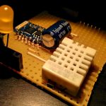
- Provide web UI for reading a temperature+humidity sensor (DHT22)
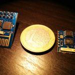
There are few different versions of the breakouts available, most popular is the DIP version . However that version only has GPIO0 and GPIO2 routed to the header, so I also purchased the SMD version that has all the pins available. I have made couple interface strip-board PCBs so that I can interface the modules with a “pure” 3.3V FTDI cable:
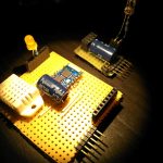
The capacitor is to provide extra juice during active WiFi operations as the FTDI cable can only provide ~50mA while bursts of Wifi may be in the area of ~200mA. I used a 1000uF capacitor on the PCBs, but a 470uF also worked with no issues.
The SMD version is more interesting, as more of the GPIO pins are available:
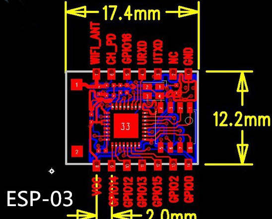
To program new firmware on the ESP-03 the following pin connections must be done:
1. CH_PD to VCC
2. GPIO02 to VCC
3. GPIO00 to GND
4. GPIO15 to GND
For normal start CH_PD to VCC and GPIO15 to GND.
Thanks to the great community at esp8266.com that project is possible with minimal effort. The esp8266 httpd project published by Sprite_tm is an incredible piece of art that allows you to run a HTTP server and simple CGI on the chip. One of the challenges with embedded systems is the difficulty in connection/misc configuration. The project overcomes this by providing a web UI that one can use to manage the settings.
If upon startup the chip isn’t able to connect to a WiFi hotspot using the saved credentials, it would automatically activate Access Point mode and you’ll be able to see “ESP_XXXXXX” where XXXXXX are the last 6 digits of the esp8266’s MAC address:
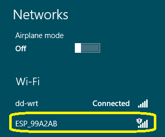
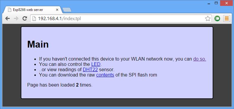
You can connect to that open AP and navigate to http://192.168.4.1 to scan for wifi networks and enter the connection password:
Main page
WiFi settings page:
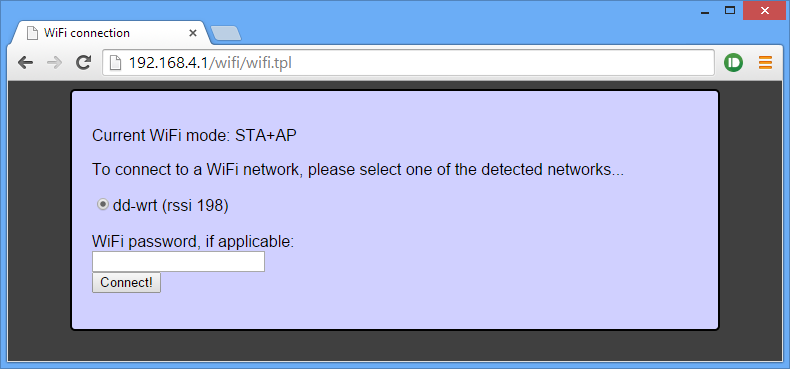 The password will be saved and from now on the module will automatically connect to that network. You don’t need to do that, all the other functions are fully accessible without the module being connected to the Internet. I can think of at least dozen use cases where that could be useful. However for my particular project, I’d need the module to be available over the Internet.
Once connected to a network, you’ll probably be wondering what the IP address of the module is. The module uses DHCP, so the address of the module will vary. You can set up a static IP lease if your router allows it, or find the ip address every time you need to use it.
I use the following linux command to find the IP address of the ESP8266 modules connected to my network:
sudo arp-scan –retry 7 –quiet –localnet –interface=wlan0 | grep -s -i 18:fe:34
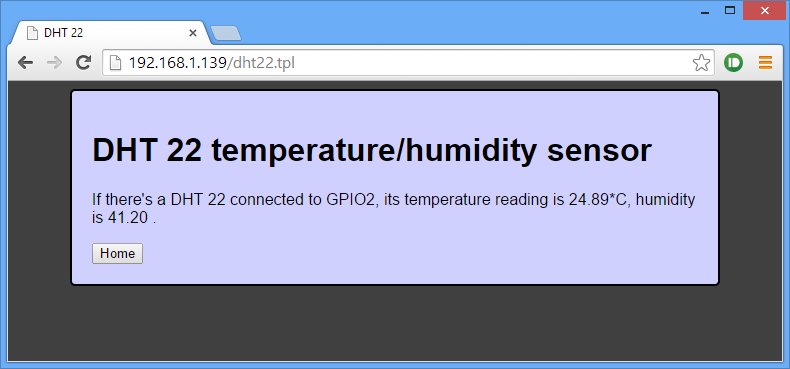
Navigating to the IP address of the module opens the same UI we were seeing before, same functionality as well. Below are the LED control and DHT22 sensor reading pages:
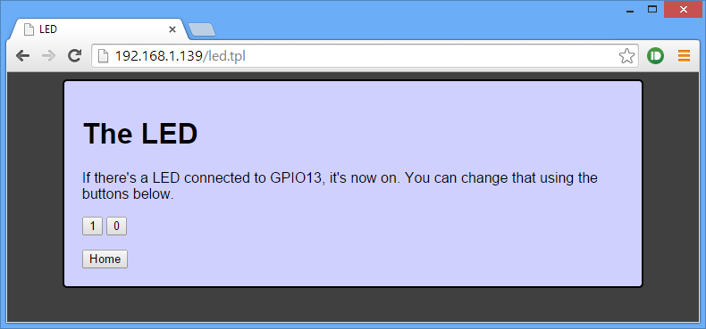
I have a LED connected to GPIO13, but that could be a relay for example.
The DHT22 page is a simple html page, but it could just be a JSON string that can be periodically polled by http://freeboard.io/ dashboard or Node-RED flow for example. The module can also be set to push the readings to a pre-configured URL at some interval; a UI interface could be set to configure destination URL, push frequency and other settings: all in my to-do list. DHT22 code by fasmide.
MQTT support on the esp8266 is a matter of time, so the web configurable settings and MQTT support will make the module excellent choice for a number of home automation tasks.
On the weaknesses side is the power consumption. During active WiFi operations it can draw up to 250mA, making battery mode quite challenging. I’ll probably stick to my ATTiny84+RFM12B nodes for low power battery operated tasks, those last more than a year on single AAA battery with a boost regulator.
The application source code is available here: app, includes the binaries so you can directly flash those without having to set up the SDK environment:
sudo ./esptool.py–port /dev/ttyUSB0 write_flash 0x00000 firmware/0x00000.bin
sudo ./esptool.py –port /dev/ttyUSB0 write_flash 0x40000 firmware/0x40000.bin
sudo ./esptool.py –port /dev/ttyUSB0 write_flash 0x12000 webpages.espfs
As a conclusion I’d say that this chip is a game changer. I am loving it and will be using it in my next home automation projects a lot.
(3313)