Quantcast
Viewing all 328 articles
Browse latest View live

JeeLabs: RFM69 on Raspberry Pi

With the Micro Power Snitch sending out packets, it’d be nice to be able to receive them!

This week is about turning a Raspberry Pi, or a similar board such as an Odroid-C1, into a Linux-based central node for what could become a home-based Wireless Sensor Network.

All it takes is an RFM69 radio module and a little soldering:

Image may be NSFW.
Clik here to view.
DSC 5086

On the menu for this week’s episode:

And before you know it, you’ll be smack in the middle of this century’s IoT craze…

(For comments, visit the forum area)


JeeLabs: RFM69 on ATmega

Now that we have the RFM69 working on Raspberry Pi and Odroid C1, we’ve got all the pieces to create a Wireless Sensor Network for home monitoring, automation, IoT, etc.

But I absolutely don’t want to leave the current range of JeeNodes behind. Moving to newer hardware should not be about making existing hardware obsolete, in my book!

Image may be NSFW.
Clik here to view.
Jnv6

The JeeNode v6 with its on-board RFM12 wireless radio module, Arduino and IDE compatibility, JeePorts, and ultra-low power consumption has been serving me well for many years, and continues to do so – with some two dozen nodes installed here at JeeLabs, each monitoring power consumption, house temperatures, room occupancy, and more. It has spawned numerous other products and DIY installations, and the open-source JeeLib library code has opened up the world of low-cost wireless signalling for many years. There are many thousands of JeeNodes out there by now.

There’s no point breaking what works. The world wastes enough technology as it is.

Which is why, long ago a special RF69-based “compatibility mode” driver was added to JeeLib, allowing the newer RFM69 modules to interoperate with the older RFM12B’s. All you have to do, is to add the following line of code to your Arduino Sketches:

#define RF69_COMPAT 1

… and the RFM69 will automagically behave like a (less featureful) RFM12.

This week is about doing the same, but in reverse: adapting JeeLib’s existing RF12 driver, which uses a specific packet format, to make an RFM12 work as if it were an RFM69:

As I’ve said, I really don’t like to break what works well. These articles will show you that there is no need. You can continue to use the RFM12 modules, and you can mix them with RFM69 modules. You can continue to use and add Arduino-compatible JeeNodes, etc. in your setup, without limiting your options to explore some of the new ARM-based designs.

Let me be clear: there are incompatibilites, and they do matter at times. Some flashy new features will not be available on older hardware. I don’t plan to implement everything on every combination, in fact I’ve been focusing more and more on ARM µC’s with RFM69 wireless, and will most likely continue to do so, simply to manage my limited time.

Long live forward compatibility, i.e. letting old hardware inter-operate with the new…

JeeLabs: Introducing the LPC824

There are more chips in NXP’s LPC8xx ARM µC family. We’ve seen the delightful 8-DIP LPC810, which packs a lot of power and is an interesting way to get started with ARM, and we’ve seen the LPC812 which is available in a tiny TSSOP-16 package, yet has 4 times the flash and RAM memory of the LPC810.

But there’s one more interesting member in this family: the LPC824, which can easily compare (and exceed) the specification of that workhorse of the Arduino world, the venerable ATmega328. This week’s episode is about getting familiar with the LPC824:

The LPC824 could make a really nice foundation for remote sensor nodes: loads of modern hardware peripherals, ultra-low sleep mode power consumption, and plenty of I/O pins.

Image may be NSFW.
Clik here to view.
Screen Shot 2015 06 01 at 15 06 59

I’m really excited about this chip. As with all the LPC8xx chips, there’s a “switch matrix” to connect (nearly) any h/w function to any pin. This means that you don’t really have to care much about pinouts and figuring out up front which pins to use for which tasks. This offers a lot of flexibility when designing general-purpose boards with a bunch of headers on them.

(For comments, visit the forum area)

mharizanov: Firmware Over The Air (FOTA) for ESP8266 SoC

With the IoT booming nowadays, the number of connected devices grows exponentially and so does the related software that drives them. There is no doubt that Firmware Over The Air (FOTA) is a highly desirable – if not required – feature for any embedded project/product both DIY or commercial. Being able to provide a remote firmware update is obviously very beneficial. The opportunity here is to enhance product functionality, operational features and provide fixes for particular issues.  Updating the firmware OTA may eliminate the need to bring a product into a service center for a repair. Although not every issue can be resolved with a firmware update, if one is available for a particular issue, it can save a lot of time and money.
I already have a large number of connected devices running at home and in case I need to do a firmware update, it is a nightmare. I have to disconnect the respective device from whatever project setup they are attached to re-program and then re-install.  Not all embedded systems have the possibility to allow FOTA due to the complexity and required connectivity, for example none of my RFM12B/RFM69CW related projects have that feature. While possible by installing additional SPI flash (see as example Moteino wireless upgrade), it isn’t a real self-updating node and still requires quite a lot of skill to achieve, and only within the range of the transceivers (not over the Internet).

The ESP8266 SoC with its WiFi connectivity is well positioned to meet that need (FOTA), my WiFi relay project would greatly benefit from it. To achieve this, the available 512KB (on most ESP8266 breakouts) on the SPI flash memory is partitioned into two, and we run code from one or the other partition. Upon FOTA, the currently not used partition gets flashed and system restarted into it:

Image may be NSFW.
Clik here to view.
ESP8266 FOTA memory layout 512MB SPI flash size

ESP8266 FOTA memory layout 512KB SPI flash size

This solution limits the available user code to 236KB (256KB-4KB-16KB); For ESP-HTTPD based projects this would be just about the unmodified basic application. Obviously if you need to squeeze in more functionality, you’d need a larger SPI flash than 512KB. There are few off-the shelf ESP8266 breakout boards with > 512KB flash size; alternatively you could desolder and replace the SPI flash with a larger one.

Firmware update modes
I can identify two separate firmware update modes – externally pushed firmware file and another one that is initiated by the remote device on periodical or manual start basis.

Push firmware update


Pull firmware update

Externally pushed firmware update would be when the device receives the firmware file over a HTTP POST request and flashes it, whereas in the self-initiated firmware update mode the device would periodically check central firmware repository for firmware update, pull the firmware and reflash itself. The later can be initiated on schedule, or manually by user (just like your computer checks for updates vs how you can manually force-check). The first method is more convenient for development mode, where the device is connected to the local network. I find it quite useful to focus on developing the code without having to manually place the node in firmware update mode, connect FTDI programmer, bring it out of firmware update mode etc. Also the speed when flashing over network connection is quite good, job gets done in roughly 10 seconds. @TVE has done great work on developing this approach with his esp-link project. Note the Makefile magic that makes all that possible.

For devices in production it makes more sense to run in the second firmware update mode, where we have them check for new firmware proactively. That also addresses connectivity issues compared to previous method as the device initiates the process from behind the firewall (no need for fixed IP address, or port forwarding for outside visibility).

That’s pretty easy to perform with SDK’s in-built functions, the following can get you going in this direction:

static void ICACHE_FLASH_ATTR ota_finished_callback(void *arg)
{
 struct upgrade_server_info *update = arg;
 if (update->upgrade_flag == true)
 {
 os_printf("[OTA]success; rebooting!\n");
 system_upgrade_reboot();
 }
 else
 {
 os_printf("[OTA]failed!\n");
 }

 os_free(update->pespconn);
 os_free(update->url);
 os_free(update);
}

static void ICACHE_FLASH_ATTR handleUpgrade(uint8_t serverVersion, const char *server_ip, uint16_t port, const char *path)
{
 const char* file;
 uint8_t userBin = system_upgrade_userbin_check();
 switch (userBin)
 {
 case UPGRADE_FW_BIN1: file = "user2.bin"; break;
 case UPGRADE_FW_BIN2: file = "user1.bin"; break;
 default:
 os_printf("[OTA]Invalid userbin number!\n");
 return;
 }

 uint16_t version=1;
 if (serverVersion <= version)
 {
 os_printf("[OTA]No update. Server version:%d, local version %d\n", serverVersion, version);
 return;
 }

 os_printf("[OTA]Upgrade available version: %d\n", serverVersion);

 struct upgrade_server_info* update = (struct upgrade_server_info *)os_zalloc(sizeof(struct upgrade_server_info));
 update->pespconn = (struct espconn *)os_zalloc(sizeof(struct espconn));

 os_memcpy(update->ip, server_ip, 4);
 update->port = port;

 os_printf("[OTA]Server "IPSTR":%d. Path: %s%s\n", IP2STR(update->ip), update->port, path, file);

 update->check_cb = ota_finished_callback;
 update->check_times = 10000;
 update->url = (uint8 *)os_zalloc(512);

 os_sprintf((char*)update->url,"GET %s%s HTTP/1.1\r\n""Host: "IPSTR":%d\r\n""Connection: close\r\n""\r\n",
 path, file, IP2STR(update->ip), update->port);

 if (system_upgrade_start(update) == false)
 {
 os_printf("[OTA]Could not start upgrade\n");

 os_free(update->pespconn);
 os_free(update->url);
 os_free(update);
 }
 else
 {
 os_printf("[OTA]Upgrading...\n");
 }
}

Here are the the two methods in action:

Image may be NSFW.
Clik here to view.
Pulling FW
Image may be NSFW.
Clik here to view.
Pushing FW

Security
In terms of security, well, it isn’t the most secure thing. Firmware gets downloaded/uploaded by unsecured HTTP channel and not much validation is performed to ensure the received file is what we think it is. I’m not sure what the overhead in terms of FLASH/RAM would be to enable SSL channel firmware upgrade. These concerns could be overcome by manually initiating an update (push or pull) and disabling the FOTA interfaces afterwards.

What could go wrong?
What can go wrong will go wrong eventually they say, so things must be handled properly. Interrupted download/upload, failed validation result in falling back to the previous firmware. The goal is obvious – to prevent a bricked device. While there is petty good protection against these, there is no protection against uploading buggy new firmware that bricks the device. Doing some testing, then some more testing and again testing before releasing new firmware should reduce the risk for that happening, and rolling it out in small portions also helps identifying a problem before many devices are affected.

Conclusion

I’m convinced the FOTA feature is a “must have” for any serious IoT project. I’m developing a FOTA capable (FOTA+ESPHTTPD+MQTT+SSL+FLASH CONFIG) platform that I will use for my future ESP8266 related projects.

  (180)

John Cantor : Temperature sensing with OpenEnergyMonitor

Temperature sensors for monitoring heat pumps


I have been using OpenEnergyMonitor.orgenergy monitors with heat pumps for a few years now and thought I should briefly share my experience.  This covers the practical side of temperature sensors, and is based on my experience.
(If you just want advice about fitting temperatures sensors onto pipes, skip further down the page)

Introduction
The sensors used in OpenEnergyMonitor.org modules are DS18b20. These are Maxim 1-wire digital sensors.
They actually have 3 connections;   0v, 5v and signal.   Since each sensor has its own unique i.d. code, multiple sensors are simply connected into the same 3 terminals on the monitor device.
The great advantage of these digital sensors is that there are no errors due to cabling.  Phone extension cable can be good enough.  Thermistor sensors (variable resistance, as PT100) rely on a specific cable resistance and furthermore some sensors could ‘drift’ out of calibration.   A further advantage of digital sensors is that they do not in themselves generate heat. They can therefore be used in still air with good accuracy.
If several sensors are strapped together (with an elastic band) and tested in a thermos flask over a few hours, most seem to read within 0.2 degrees C of each other.  If you have say 6 sensors, you can chose those that agree most for the most important sensing (e.g. flow and return).   Anyhow, these sensors are perfectly accurate enough for this type of monitoring, and there is comfort in knowing that if you are seeing 35.2C (for example) on a graph, then that sensor tip must be at 35.2 +/-, with a small error margin of say 0.15 degrees.  This is because the digital signal is generated inside the sensor.

What to measure on a heat pump?

Typical temperature measurement could include the following
Ground source
Water flow and water return from heat pump (hot side)
Glycol inlet and outlet from heat pump (cold side) 
outside (ambient) air temperature.  
Hot water cylinder temperature. And at least one room temperature.

Air source
Water flow and water return from heat pump (hot side)
outside (ambient) air temperature and air-off (cooled air leaving heat pump) 
Hot water cylinder temperature. And at least one room temperature.
For either of the above there could be a buffer cylinder involved in the design, therefore the flow and return from buffer cylinder to emitter (e.g. underfloor or radiators) may need to be monitored.
There may also be mixing valves (sometimes unnecessary mixing valves) on underfloor manifolds. These may need monitoring.

For more detailed analysis, the refrigerant internals of the heat pump can be monitored. These may include discharge, suction and liquid temperatures.   This is however a little intrusive, and could affect the warranty. It may be necessary to discuss this with the system installers.

Measuring air and liquids 

Air

Measuring internal air temperature is relatively straight forward, but sensors must be positioned away from any source of heat or radiation source.  Sunlight and close-by appliances and lighting can greatly affect readings.  The general rule for outside air measurement is to keep the sensor well away from sunshine, or areas that get sunshine.  The sensor can also drop below the air temperature if it can ‘see’ a clear sky.  A small polystyrene roof is a good shield protection from positive or ‘negative’ radiation (i.e. when radiation from sensor is greater than its surroundings).  It is also necessary to keep the sensor dry, unless you purposefully wish to cover it with a wet ‘sock’ to record Wet Bulb Temperature.  There is a lot of information available about this relating to weather stations.


Liquids

Most heat pump monitoring involves the temperature measurement of water and liquids flowing in the pipes.
For very high accuracy results, as required by heat meter devices, an immersion pocket is required. (Heat Meters measure the difference between two sensors, so both must be very accurate)
The pocket usually involves a ‘tee’ fitting and a hollow pocket that is completely surrounded by the liquid. The sensor is inserted into the pocket.
An easier and cheaper method is to fix the sensor to the outside of a metal pipe. This method is used in all heat pumps for their on-board sensing.
Any sensor that is outside the liquid can be affected by the temperature of the surrounding air, but the error in the reading can be negligible if the sensor is mounted correctly.


There are various methods as follows-
1)  Sensor strapped to metal pipe or metal fitting
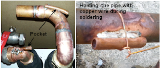
2) Sensor inserted in surface pocket (a pipe soldered to the pipe’s surface)


This shows 10mm pipes that have been soft-soldered to copper fittings. Due to the high conductivity of copper, the temperature of the inside of the small pipe is almost exactly the same as the temperature of the liquid inside the pipe. After insulating (lagging) this pipe, the accuracy of the sensor inserted inside the small pipe should be excellent.  Ideally the pocket internal diameter is close to the sensor diameter.  Conductive paste should be used before inserting the sensor
It is a good idea to fit several pockets like this in the right places during installation. Obviously the pipe must be empty.
Many heat pump manufacturers solder pipes on the outside of water or refrigerant pipes so that their sensor probes can easily be inserted to give accurate measurement


Strapping a sensor to a pipe (or a pipe fitting)


Copper or brass conduct heat well.  The temperature difference between the inside of the pipe and the outside is tiny, so always fit sensors onto metals.  Plastic pipes are poor thermal conductors, so the effect of surrounding air can affect the sensor temperature. Furthermore, if the pipe is changing in temperature, the sensor may ‘lag’ behind. i.e. it will respond very slowly to temperature changes.  This may or may not be a problem.

This is not the best sensor position for a sensor since there is 3mm of plastic between the liquid inside and the probe, however, the copper wire strap is making the best of a bad job.  Heat will conduct along the copper. There is a lot of copper in contact with the plastic, and this will conduct and will transfer heat to/from the ‘surrounded’ probe.  If this is insulated well on the outside, it may give good-enough results.  Time response may be a little slow, which is not necessarily bad.   Fitting the probe onto a metal fitting is probably a better bet.

JeeLabs: Code for the LPC8xx

Putting a chip on a board, as with the Tinker Pico, is one thing. Getting it to do something is quite another matter. We’ll want to develop tons of software for it and upload the code.

Image may be NSFW.
Clik here to view.
DSC 5118

The uploading bit has already been solved by using a modified FTDI board, with some exciting new options coming up in the next few months. How’s that for a teaser, eh?

This week’s episode is about the software side of things. Toolchains, runtimes, build tools, IDE’s, that sort of thing. Brought to you – as usual – in a series of daily bite-sized articles:

I’m having a hard time making up my mind on which path to choose as future code base. The curse of having too many choices, each with their own trade-offs and compromises.

(For comments, visit the forum area)

mharizanov: Some thoughts on security in terms of IoT


Connected devices and sensors are the fastest growing sources of data. Billions of records are being generated daily around the globe and data transported across networks to be consumed where needed. Security of data in transit or at still in that context (especially when it comes to sensitive personal data) is quite important.

Back in 2011 Fitbit portal exposed on the Internet thousands of records of intimate activities of their subscribers. How did that affect the company’s reputation and customer trust? Damage is done to the whole IoT industry, not just the company that allowed that to happen.

As customers we want our data encrypted during transport, stored safely and kept private. The collation of multiple points of data can quickly become personal information as events are reviewed in the context of location, time, recurrence, etc. The regular purchase of different food types, for example, may reveal religion or ongoing health concerns. Health records, location details, energy use patterns and so forth private data can easily be used to reconstruct in great detail one’s life. This data is therefore naturally of interest to many. Governments, insurance companies, marketing/advertising agencies and certainly criminals are after it.

Unauthorized access to data isn’t the only problem. Connected devices are designed to be remotely controllable. With surprisingly many consumers relying on default product security credentials, it is strikingly easy to gain control of connected appliances. Dynamic DNS services are a honeypot to those hunting for connected devices. One could easily end up with a spying thermostat or a fridge that sends spam or someone remotely controlling your smart home.

What makes it so hard to get security right? Design flaws, implementation flaws and mismanagement  are often the source of vulnerabilities. šSystems are “adequately secure” only relative to a perceived threat. šAbsence of obvious insecurities is not a good indication that a system is adequately secure. Users also have a good share in decreased security by not updating firmware, using poor passwords, inadequate fire-walling. “Security” through obscurity is very common and seems that folks still believe in it.

Overall security concerns are at the top of the list of barriers to the IoT adoption, with consumers awareness in this area on the rise. Any IoT business model must adequately address these concerns in order to be successful and sustainable.

  (92)

JeeLabs: Moving up a (few) level(s)

All the posts and articles so far have been about staying “close to the silicon” on ARM µCs. Direct access to I/O registers to control and read out pins, and to activate the built-in hardware interfaces. It gets tedious after a while, and worst of all: very repetitive.

I’ve been coding for the LPC8xx chips in C/C++ with virtually no runtime library support. The reason was to expose all the raw stuff that happens as a µC starts up, very dumb, and needs to be told how to get a notion of time (SysTick), how to read/set/clear/toggle pins, how to sleep in various low-power modes, how to talk to the serial interface, yada, yada…

Figuring out how things work at the lowest level is a fascinating adventure. It’s no more than an indirect jump on reset, a run-time stack, and processing machine code – forever. But let’s not deal with these details all the time. Let’s think about sensors, conditions, decisions, actions – let’s define the behaviour of a system, not just deal with technicalities.

There are numerous ways to move up in abstraction level on embedded µCs. This week’s episode is about the bigger picture and the three broad categories of these approaches:

Warning: there are no conclusions at the end. I’m still exploring and evaluating. I’ve been on many long and winding roads already. I’m not too impressed by most of them. Treating a µC (any board) as the centre of a project feels wrong, particularly in the context of multi-node home monitoring and automation – which is still, after all, the focus of this weblog.

We really need to look at the bigger picture. How to evolve and manage the designs we create over a longer period of time. Old stuff needs to fit in, but it shouldn’t prevent us from finding a broader view. Adding and managing single nodes should not be the main focus.

(For comments, visit the forum area)


mharizanov: Tweeting silicon

Here is a fun project for I did couple days ago: a tweeting ESP8266. The typical approach when dealing with such task (and probably the better) is to use a proxy service like ThingSpeak’s ThingTweetPushingBox or by building proxy yourself with Node-RED or mqttwarn. It is much more fun though to perform a direct tweet from a microcontroller. Just think about the complexity of using TLS and oAuth along with Twitter’s API, all that done from a $5 Wi-Fi connected SoC..

Getting this done was pretty much straight forward except for the hmac-sha1 hashing of the oAuth base string. Turned out that the hmac-sha1 implementation in ESP8266’s SDK only supports 64 byte keys, while I was getting a much larger key. Wikipedia’s article on hmac-sha1 hashing shows the approach to that case and I was able to generate a correct hash with one additional SHA1 applied to the key to reduce it to 20 bytes.

if (length(key) > blocksize) then
        key = hash(key) // keys longer than blocksize are shortenedend if

So my ESP8266 can now  tweet, I created a dedicated Twitter account for it named “Tweeting silicon” @tweetingsilicon

Image may be NSFW.
Clik here to view.
tweeting_silicon

Code for the project is available on Github. Code is dirty, please contribute to improve it.


  (106)

FairTradeElectronics: Take a Look at the Best rice cookers

Rice is a type of grain that we can cook and consume with a stew of our choice. It is very versatile and can be cooked in various ways. Today, there are appliances that can cook rice automatically. They save us time and are very convenient. Here are the best rice cookers in the market.

Aroma

The Aroma rice cooker is heralded as one of the best in the market. It is an affordable appliance that cooks your rice very quickly and makes it super delicious. It is simple to use and has a high capacity. The Aroma rice cookers come in 3 varieties. These are the 6 cup, 8 cup and 20 cup cookers. The 6 cup cooker costs $15 to $25, the 8 cup costs $25 to $35 and the 20 cup costs $30 to $100. All of them can easily steam food and are made of stainless steel. One major advantage of getting this Aroma rice cooker is that you can cook the rice and another dish in it at the same time. You can steam some meat while the rice cooks under it. It also makes use of digital technology. You can set it to activate itself and start cooking after a specific number of hours. Thus, you can load it with rice as you leave the house in the morning and when you get home you’ll find that it has already cooked for you.

Instant Pot

This is another type of rice cooker that is simply amazing to use. This rice cooker can make almost all types of rice for example Spanish rice. In addition to that, it can be programmed to cook your rice after a set number of hours. In addition to rice, this amazing cooker can prepare soups, beans, meat, poultry and stew. All these will get ready to eat in a very short amount of time. It has a capacity of 6 quarts. For only $135 to $235, the Instant Pot rice cooker is definitely one of the best available.

Cuckoo rice cooker

In terms of style and design, the cuckoo rice cooker bests its competitors by far. It has a round, ergonomic shape that is appealing to touch. Moreover, it is very capable in its ability to cook for you. It has a capacity of 6 cups. Its size is compact and it can easily be carried in luggage during trips. The cooker can easily and effectively cook brown and white rice. For an affordable price of $80 to $120, the Cuckoo rice cooker is a great choice of rice cooker.

Miracle rice cooker

Made of stainless steel and colored in pearl white, this rice cooker is one of the shoppers’ favorite. It costs from $70 to $90. In it, there is a high quality steamer for vegetables as well as a stainless steel bowl. It has a capacity of 8 cups of rice. You can easily cook the rice and steam your vegetables at the same time. This ability will save you a lot of time when preparing meals since you can do it all in one go. Thus, it is a multitasking rice cooker for a very affordable price.

Visit this site for more detailed rice cooker reviews: http://www.ricecookersportal.org/ and be quick cause those amazing deals don’t last forever!

FairTradeElectronics: Your Mercedes Dealer In Chelmsford

The Mercedes Benz of Chelmsford car dealership is a part of the Jardine Motors Group in the UK which trades under the brand name Lancaster. Jardine Motors Group UK has grown from a family-run car dealer to become a large car dealer representing 23 manufacturers all over Europe. It has 70 different locations dealing in different car brands including one in Chelmsford which specializes in Mercedes Benz retail. Other sites are found at Lakeside, Southend, Colchester, Ipswich and others. The Jardine Motor Group is one of the largest and prestigious automotive retail groups in the country. It is a reputable dealership that has kept a loyal client base and has become the first choice for customers. Mercedes Chelmsford deals in selling new and approved used Benz cars as well as their parts. It provides a friendly environment for its customers as well as offer impeccable care and services. The dealership is stocked excellently with cars ranging from stunning previously owned ones to the very latest releases of the brand. There are over 550 Approved Used Mercedes Benz gracing their extensive stock. The customer is given a variety of colour to choose from when going in to shop for a new car. To spice it all up, the dealer offers its clients unbelievably affordable prices with their flexible finance plans which opens up one’s accessibility to a wider choice of car models. The staff is not only friendly but also has expertise on the Mercedes Benz and are passionate about the brand. Their knowledge is vast and can match the client’s requirements comfortably. Mercedes Chelmsford also has a MyService waiting area complete with free Wi-Fi so that you are occupied and entertained while waiting for your car to get serviced at their site. There are also quality refreshments one can buy while waiting to have the client feeling comfortable. The Business Zone also has an enclosed workspace that clients can utilize when waiting. The Mercedes Benz of Chelmsford showroom is not hard to find. It is located on the White Hart Lane in Springfield Chelmsford on the roundabout opposite Sainsbury. The airy and bright showroom is easy to spot from the road with the forecourt for the new and the approved used Mercedes Benz cars. The location is convenient with close links to various other locations such as East London, Hatfield Peveral, Boreham, Witham, Woodham, Brentwood, Shenfield, Ingatestone, Broomfield among others. Stock delivery can be done across England, Wales, Scotland and Northern Ireland to all of the UK whether for business use or personal use. Their Customer Service is also exceptional. Aftersales services are offered in full complement by their state of the art facilities to keep your Mercedes Benz in excellent condition. The expertly trained staff on the Mercedes Benz attend to your car only with Mercedes Genuine Parts so that you are assured that your car is in the best condition and being properly taken care of. Say goodbye to the hustle that comes with shopping for a good affordable car, whether new or a decent used Mercedes Benz and give Mercedes Chelmsford a call.

FairTradeElectronics: Ultimate guide to buying a water softener system

There are a good number of water softener manufacturing companies on the market; this can compromise quality. If there is anything that one should not get close to compromising is health. Drinking water should be clean, that is not debatable, treated with the appropriate softener moreover soft water will save you a lot in terms of the soap used to clean, heating elements like the kettle will not form layers and all water related chores will be smoother. This article will provide you a guide to buying the best softener for your water from the diverse water softener providing companies.

The first thing you need to know is how much you will spend on the services, www.watersoftenersnow.org says it doesn’t have to be expensive. You should not overpay for water softener service due to the desperateness of installing the best water softener. You need to understand the pricing so that you invest in an affordable system that in future, it can recoup the investment. Therefore, the key point is you understand the costs of various systems on the market.

How much do you need to efficiently and effectively run the system? An answer to this question provides you with an ability to know a system you can choose. The energy needed to run the system should not greatly on impact your budget. You can decide to venture into non-electrical systems if you realize that water and electrical bills will strain your budget. However, if you are comfortable with the bills then that should not be a pointer.

Size of the equipment is another pointer in the guide to purchasing a water softener system.you will need to take measurements of your compound. Water usage and plumbing measurements will help you realize if the system you are going to purchase is adequate. You should not purchase a system that will be ineffective. If you have a bigger compound with a lot of water utilizing processes then definitely you will suffocate your water needs.

How large is the space you are intending to install your system on? If you overestimate or underestimate your space, definitely you will suffer costs. You will stand higher chances of purchasing a suitable system when you provide as much information as you can. Do not buy something too large for your compound under the pressure of need of a larger system. You can save money by having the appropriate sized system.

Research! Research! Research! Key to getting the best company for the best water softener system is by researching among the available ones. First, it must be licensed, should be insured and bonded. Secondly, you can consider referrals from clients and finally read all reviews left by customers who have installed the systems. Those who have had the system for longer periods should be at a position to judge better.

Are you buying the equipment on you want your supplier to provide them? This is also a factor to consider. Plumber or dealer is inclusive in the instruments. Buying the equipment online translates to installing the equipment on your own. You choose a system after settling on a particular company. This should put you at a position to choose a water softening system that will serve you well.

mharizanov: Firmware Over The Air (FOTA) for ESP8266 SoC

With the IoT booming nowadays, the number of connected devices grows exponentially and so does the related software that drives them. There is no doubt that Firmware Over The Air (FOTA) is a highly desirable – if not required – feature for any embedded project/product both DIY or commercial. Being able to provide a remote firmware update is obviously very beneficial. The opportunity here is to enhance product functionality, operational features and provide fixes for particular issues.  Updating the firmware OTA may eliminate the need to bring a product into a service center for a repair. Although not every issue can be resolved with a firmware update, if one is available for a particular issue, it can save a lot of time and money.
I already have a large number of connected devices running at home and in case I need to do a firmware update, it is a nightmare. I have to disconnect the respective device from whatever project setup they are attached to re-program and then re-install.  Not all embedded systems have the possibility to allow FOTA due to the complexity and required connectivity, for example none of my RFM12B/RFM69CW related projects have that feature. While possible by installing additional SPI flash (see as example Moteino wireless upgrade), it isn’t a real self-updating node and still requires quite a lot of skill to achieve, and only within the range of the transceivers (not over the Internet).

The ESP8266 SoC with its WiFi connectivity is well positioned to meet that need (FOTA), my WiFi relay project would greatly benefit from it. To achieve this, the available 512KB (on most ESP8266 breakouts) on the SPI flash memory is partitioned into two, and we run code from one or the other partition. Upon FOTA, the currently not used partition gets flashed and system restarted into it:

Image may be NSFW.
Clik here to view.
ESP8266 FOTA memory layout 512MB SPI flash size

ESP8266 FOTA memory layout 512KB SPI flash size

This solution limits the available user code to 236KB (256KB-4KB-16KB); For ESP-HTTPD based projects this would be just about the unmodified basic application. Obviously if you need to squeeze in more functionality, you’d need a larger SPI flash than 512KB. There are few off-the shelf ESP8266 breakout boards with > 512KB flash size; alternatively you could desolder and replace the SPI flash with a larger one.

Firmware update modes
I can identify two separate firmware update modes – externally pushed firmware file and another one that is initiated by the remote device on periodical or manual start basis.

Push firmware update


Pull firmware update

Externally pushed firmware update would be when the device receives the firmware file over a HTTP POST request and flashes it, whereas in the self-initiated firmware update mode the device would periodically check central firmware repository for firmware update, pull the firmware and reflash itself. The later can be initiated on schedule, or manually by user (just like your computer checks for updates vs how you can manually force-check). The first method is more convenient for development mode, where the device is connected to the local network. I find it quite useful to focus on developing the code without having to manually place the node in firmware update mode, connect FTDI programmer, bring it out of firmware update mode etc. Also the speed when flashing over network connection is quite good, job gets done in roughly 10 seconds. @TVE has done great work on developing this approach with his esp-link project. Note the Makefile magic that makes all that possible.

For devices in production it makes more sense to run in the second firmware update mode, where we have them check for new firmware proactively. That also addresses connectivity issues compared to previous method as the device initiates the process from behind the firewall (no need for fixed IP address, or port forwarding for outside visibility).

That’s pretty easy to perform with SDK’s in-built functions, the following can get you going in this direction:

static void ICACHE_FLASH_ATTR ota_finished_callback(void *arg)
{
 struct upgrade_server_info *update = arg;
 if (update->upgrade_flag == true)
 {
 os_printf("[OTA]success; rebooting!\n");
 system_upgrade_reboot();
 }
 else
 {
 os_printf("[OTA]failed!\n");
 }

 os_free(update->pespconn);
 os_free(update->url);
 os_free(update);
}

static void ICACHE_FLASH_ATTR handleUpgrade(uint8_t serverVersion, const char *server_ip, uint16_t port, const char *path)
{
 const char* file;
 uint8_t userBin = system_upgrade_userbin_check();
 switch (userBin)
 {
 case UPGRADE_FW_BIN1: file = "user2.bin"; break;
 case UPGRADE_FW_BIN2: file = "user1.bin"; break;
 default:
 os_printf("[OTA]Invalid userbin number!\n");
 return;
 }

 uint16_t version=1;
 if (serverVersion <= version)
 {
 os_printf("[OTA]No update. Server version:%d, local version %d\n", serverVersion, version);
 return;
 }

 os_printf("[OTA]Upgrade available version: %d\n", serverVersion);

 struct upgrade_server_info* update = (struct upgrade_server_info *)os_zalloc(sizeof(struct upgrade_server_info));
 update->pespconn = (struct espconn *)os_zalloc(sizeof(struct espconn));

 os_memcpy(update->ip, server_ip, 4);
 update->port = port;

 os_printf("[OTA]Server "IPSTR":%d. Path: %s%s\n", IP2STR(update->ip), update->port, path, file);

 update->check_cb = ota_finished_callback;
 update->check_times = 10000;
 update->url = (uint8 *)os_zalloc(512);

 os_sprintf((char*)update->url,"GET %s%s HTTP/1.1\r\n""Host: "IPSTR":%d\r\n""Connection: close\r\n""\r\n",
 path, file, IP2STR(update->ip), update->port);

 if (system_upgrade_start(update) == false)
 {
 os_printf("[OTA]Could not start upgrade\n");

 os_free(update->pespconn);
 os_free(update->url);
 os_free(update);
 }
 else
 {
 os_printf("[OTA]Upgrading...\n");
 }
}

Here are the the two methods in action:

Image may be NSFW.
Clik here to view.
Pulling FW
Image may be NSFW.
Clik here to view.
Pushing FW

Security
In terms of security, well, it isn’t the most secure thing. Firmware gets downloaded/uploaded by unsecured HTTP channel and not much validation is performed to ensure the received file is what we think it is. I’m not sure what the overhead in terms of FLASH/RAM would be to enable SSL channel firmware upgrade. These concerns could be overcome by manually initiating an update (push or pull) and disabling the FOTA interfaces afterwards.

What could go wrong?
What can go wrong will go wrong eventually they say, so things must be handled properly. Interrupted download/upload, failed validation result in falling back to the previous firmware. The goal is obvious – to prevent a bricked device. While there is petty good protection against these, there is no protection against uploading buggy new firmware that bricks the device. Doing some testing, then some more testing and again testing before releasing new firmware should reduce the risk for that happening, and rolling it out in small portions also helps identifying a problem before many devices are affected.

Conclusion

I’m convinced the FOTA feature is a “must have” for any serious IoT project. I’m developing a FOTA capable (FOTA+ESPHTTPD+MQTT+SSL+FLASH CONFIG) platform that I will use for my future ESP8266 related projects.

  Page views: 84419

mharizanov: Some thoughts on security in terms of IoT


Connected devices and sensors are the fastest growing sources of data. Billions of records are being generated daily around the globe and data transported across networks to be consumed where needed. Security of data in transit or at still in that context (especially when it comes to sensitive personal data) is quite important.

Back in 2011 Fitbit portal exposed on the Internet thousands of records of intimate activities of their subscribers. How did that affect the company’s reputation and customer trust? Damage is done to the whole IoT industry, not just the company that allowed that to happen.

As customers we want our data encrypted during transport, stored safely and kept private. The collation of multiple points of data can quickly become personal information as events are reviewed in the context of location, time, recurrence, etc. The regular purchase of different food types, for example, may reveal religion or ongoing health concerns. Health records, location details, energy use patterns and so forth private data can easily be used to reconstruct in great detail one’s life. This data is therefore naturally of interest to many. Governments, insurance companies, marketing/advertising agencies and certainly criminals are after it.

Unauthorized access to data isn’t the only problem. Connected devices are designed to be remotely controllable. With surprisingly many consumers relying on default product security credentials, it is strikingly easy to gain control of connected appliances. Dynamic DNS services are a honeypot to those hunting for connected devices. One could easily end up with a spying thermostat or a fridge that sends spam or someone remotely controlling your smart home.

What makes it so hard to get security right? Design flaws, implementation flaws and mismanagement  are often the source of vulnerabilities. šSystems are “adequately secure” only relative to a perceived threat. šAbsence of obvious insecurities is not a good indication that a system is adequately secure. Users also have a good share in decreased security by not updating firmware, using poor passwords, inadequate fire-walling. “Security” through obscurity is very common and seems that folks still believe in it.

Overall security concerns are at the top of the list of barriers to the IoT adoption, with consumers awareness in this area on the rise. Any IoT business model must adequately address these concerns in order to be successful and sustainable.

  Page views: 1227

mharizanov: Tweeting silicon

Here is a fun project for I did couple days ago: a tweeting ESP8266. The typical approach when dealing with such task (and probably the better) is to use a proxy service like ThingSpeak’s ThingTweetPushingBox or by building proxy yourself with Node-RED or mqttwarn. It is much more fun though to perform a direct tweet from a microcontroller. Just think about the complexity of using TLS and oAuth along with Twitter’s API, all that done from a $5 Wi-Fi connected SoC..

Getting this done was pretty much straight forward except for the hmac-sha1 hashing of the oAuth base string. Turned out that the hmac-sha1 implementation in ESP8266’s SDK only supports keys of size less the block size (64 bytes), while Twitter needs much larger key for the signature. Wikipedia’s article on hmac-sha1 hashing explains the approach to that case and I was able to generate a correct hash with one additional SHA1 applied to the key to reduce it to 20 bytes.

if (length(key) > blocksize) then
        key = hash(key) // keys longer than blocksize are shortenedend if

So my ESP8266 can now  tweet, I created a dedicated Twitter account for it named “Tweeting silicon” @tweetingsilicon

Image may be NSFW.
Clik here to view.
tweeting_silicon

Code for the project is available on Github. Code is dirty, please contribute to improve it.


  Page views: 848


JeeLabs: FTDI over WiFi: esp-bridge

Time to try something different – this week, the JeeLabs blog and articles will be written by Thorsten von Eicken, as guest author. I’m very excited by the project he has created and will gladly step aside to let him introduce it all -jcw

Has it ever happened to you that you put together a nice JeeNode or Arduino project, test it all out on your bench, then mount it “in the field” and … it doesn’t quite work right? Or the next day it malfunctions? Well, to me it happens all the time. Or I want to add another feature to my greenhouse controller or my weather station but I don’t want to bring it back to my bench for a few days for a full rework and re-test. Instead I’d love to troubleshoot or tune the code remotely, sitting comfortably at home in the evening while my project is mounted somewhere out there.

My first attempt at solving this situation was to deploy a BeagleBone Black with a WiFi dongle and a serial cable (a RaspberryPi or Odroid could work just as well):

Image may be NSFW.
Clik here to view.
20150622 112023  1

Essentially I turned a $55 BBB plus a little $10 WiFi dongle into a remote FTDI widget. In the first moment I was in heaven: it’s an inexpensive solution in the grand scheme of things and it worked great. But then I became addicted and one BBB was insufficient: I wanted to hook more than one remote JeeNode up! Well, suddenly the prospect of buying 3-4 such set-ups didn’t look so inexpensive anymore!

That’s when the esp8266 WiFi modules caught my eye at a cost under $5. Here is a WiFi module with a processor and a UART and, most importantly, an SDK (software development kit). The SDK suggested that I could implement the key functions to remotely watch debug output of a JeeNode as well as reprogram it, just like I was doing with the BBB. My mind started racing: what could I make it do? What would a complete hardware solution cost? How much power would it use? What is its WiFi range?

Image may be NSFW.
Clik here to view.
DSC 5121

At that point I chatted with JC about my little project, which I called “esp-bridge”, and got a cautiously interested response with ingredients ranging from “sounds very cool!” to “it’s gonna use way too much power”. Not to be easily deterred I thought it would take me about a week to write some code. That was 4 months ago, and while I have a day job I have spent a lot of time on the esp-bridge project since. In the end, I hope you will benefit from all this because through this week’s episode of the JeeLabs blog you will indeed be able to complete the journey in one week! The plan for the week is as follows:

As the week develops (and beyond) I would love to hear your feedback and questions. The last post will be written just-in-time so I can try to answer anything that comes up before then. For general discussion, please use the esp-link thread on the ESP8266.com site or open a new thread in the same forum. If you download the software from GitHub to put your own esp-bridge together and run into bugs or mis-features please post to the GitHub issues tracker.

Quick clarifications about names: esp-bridge refers to the hardware & software gadget described in this blog series while esp-link is the name of the software itself.

(For comments, visit the forum area)

mharizanov: Firmware Over The Air (FOTA) for ESP8266 SoC

With the IoT booming nowadays, the number of connected devices grows exponentially and so does the related software that drives them. There is no doubt that Firmware Over The Air (FOTA) is a highly desirable – if not required – feature for any embedded project/product both DIY or commercial. Being able to provide a remote firmware update is obviously very beneficial. The opportunity here is to enhance product functionality, operational features and provide fixes for particular issues.  Updating the firmware OTA may eliminate the need to bring a product into a service center for a repair. Although not every issue can be resolved with a firmware update, if one is available for a particular issue, it can save a lot of time and money.
I already have a large number of connected devices running at home and in case I need to do a firmware update, it is a nightmare. I have to disconnect the respective device from whatever project setup they are attached to re-program and then re-install.  Not all embedded systems have the possibility to allow FOTA due to the complexity and required connectivity, for example none of my RFM12B/RFM69CW related projects have that feature. While possible by installing additional SPI flash (see as example Moteino wireless upgrade), it isn’t a real self-updating node and still requires quite a lot of skill to achieve, and only within the range of the transceivers (not over the Internet).

The ESP8266 SoC with its WiFi connectivity is well positioned to meet that need (FOTA), my WiFi relay project would greatly benefit from it. To achieve this, the available 512KB (on most ESP8266 breakouts) on the SPI flash memory is partitioned into two, and we run code from one or the other partition. Upon FOTA, the currently not used partition gets flashed and system restarted into it:

Image may be NSFW.
Clik here to view.
ESP8266 FOTA memory layout 512MB SPI flash size

ESP8266 FOTA memory layout 512KB SPI flash size

This solution limits the available user code to 236KB (256KB-4KB-16KB); For ESP-HTTPD based projects this would be just about the unmodified basic application. Obviously if you need to squeeze in more functionality, you’d need a larger SPI flash than 512KB. There are few off-the shelf ESP8266 breakout boards with > 512KB flash size; alternatively you could desolder and replace the SPI flash with a larger one.

Firmware update modes
I can identify two separate firmware update modes – externally pushed firmware file and another one that is initiated by the remote device on periodical or manual start basis.

Push firmware update


Pull firmware update

Externally pushed firmware update would be when the device receives the firmware file over a HTTP POST request and flashes it, whereas in the self-initiated firmware update mode the device would periodically check central firmware repository for firmware update, pull the firmware and reflash itself. The later can be initiated on schedule, or manually by user (just like your computer checks for updates vs how you can manually force-check). The first method is more convenient for development mode, where the device is connected to the local network. I find it quite useful to focus on developing the code without having to manually place the node in firmware update mode, connect FTDI programmer, bring it out of firmware update mode etc. Also the speed when flashing over network connection is quite good, job gets done in roughly 10 seconds. @TVE has done great work on developing this approach with his esp-link project. Note the Makefile magic that makes all that possible.

For devices in production it makes more sense to run in the second firmware update mode, where we have them check for new firmware proactively. That also addresses connectivity issues compared to previous method as the device initiates the process from behind the firewall (no need for fixed IP address, or port forwarding for outside visibility).

That’s pretty easy to perform with SDK’s in-built functions, the following can get you going in this direction:

static void ICACHE_FLASH_ATTR ota_finished_callback(void *arg)
{
 struct upgrade_server_info *update = arg;
 if (update->upgrade_flag == true)
 {
 os_printf("[OTA]success; rebooting!\n");
 system_upgrade_reboot();
 }
 else
 {
 os_printf("[OTA]failed!\n");
 }

 os_free(update->pespconn);
 os_free(update->url);
 os_free(update);
}

static void ICACHE_FLASH_ATTR handleUpgrade(uint8_t serverVersion, const char *server_ip, uint16_t port, const char *path)
{
 const char* file;
 uint8_t userBin = system_upgrade_userbin_check();
 switch (userBin)
 {
 case UPGRADE_FW_BIN1: file = "user2.bin"; break;
 case UPGRADE_FW_BIN2: file = "user1.bin"; break;
 default:
 os_printf("[OTA]Invalid userbin number!\n");
 return;
 }

 uint16_t version=1;
 if (serverVersion <= version)
 {
 os_printf("[OTA]No update. Server version:%d, local version %d\n", serverVersion, version);
 return;
 }

 os_printf("[OTA]Upgrade available version: %d\n", serverVersion);

 struct upgrade_server_info* update = (struct upgrade_server_info *)os_zalloc(sizeof(struct upgrade_server_info));
 update->pespconn = (struct espconn *)os_zalloc(sizeof(struct espconn));

 os_memcpy(update->ip, server_ip, 4);
 update->port = port;

 os_printf("[OTA]Server "IPSTR":%d. Path: %s%s\n", IP2STR(update->ip), update->port, path, file);

 update->check_cb = ota_finished_callback;
 update->check_times = 10000;
 update->url = (uint8 *)os_zalloc(512);

 os_sprintf((char*)update->url,"GET %s%s HTTP/1.1\r\n""Host: "IPSTR":%d\r\n""Connection: close\r\n""\r\n",
 path, file, IP2STR(update->ip), update->port);

 if (system_upgrade_start(update) == false)
 {
 os_printf("[OTA]Could not start upgrade\n");

 os_free(update->pespconn);
 os_free(update->url);
 os_free(update);
 }
 else
 {
 os_printf("[OTA]Upgrading...\n");
 }
}

Here are the the two methods in action:

Image may be NSFW.
Clik here to view.
Pulling FW
Image may be NSFW.
Clik here to view.
Pushing FW

Security
In terms of security, well, it isn’t the most secure thing. Firmware gets downloaded/uploaded by unsecured HTTP channel and not much validation is performed to ensure the received file is what we think it is. I’m not sure what the overhead in terms of FLASH/RAM would be to enable SSL channel firmware upgrade. These concerns could be overcome by manually initiating an update (push or pull) and disabling the FOTA interfaces afterwards.

What could go wrong?
What can go wrong will go wrong eventually they say, so things must be handled properly. Interrupted download/upload, failed validation result in falling back to the previous firmware. The goal is obvious – to prevent a bricked device. While there is petty good protection against these, there is no protection against uploading buggy new firmware that bricks the device. Doing some testing, then some more testing and again testing before releasing new firmware should reduce the risk for that happening, and rolling it out in small portions also helps identifying a problem before many devices are affected.

Conclusion

I’m convinced the FOTA feature is a “must have” for any serious IoT project. I’m developing a FOTA capable (FOTA+ESPHTTPD+MQTT+SSL+FLASH CONFIG) platform that I will use for my future ESP8266 related projects.

  Page views: 84499

mharizanov: Some thoughts on security in terms of IoT


Connected devices and sensors are the fastest growing sources of data. Billions of records are being generated daily around the globe and data transported across networks to be consumed where needed. Security of data in transit or at still in that context (especially when it comes to sensitive personal data) is quite important.

Back in 2011 Fitbit portal exposed on the Internet thousands of records of intimate activities of their subscribers. How did that affect the company’s reputation and customer trust? Damage is done to the whole IoT industry, not just the company that allowed that to happen.

As customers we want our data encrypted during transport, stored safely and kept private. The collation of multiple points of data can quickly become personal information as events are reviewed in the context of location, time, recurrence, etc. The regular purchase of different food types, for example, may reveal religion or ongoing health concerns. Health records, location details, energy use patterns and so forth private data can easily be used to reconstruct in great detail one’s life. This data is therefore naturally of interest to many. Governments, insurance companies, marketing/advertising agencies and certainly criminals are after it.

Unauthorized access to data isn’t the only problem. Connected devices are designed to be remotely controllable. With surprisingly many consumers relying on default product security credentials, it is strikingly easy to gain control of connected appliances. Dynamic DNS services are a honeypot to those hunting for connected devices. One could easily end up with a spying thermostat or a fridge that sends spam or someone remotely controlling your smart home.

What makes it so hard to get security right? Design flaws, implementation flaws and mismanagement  are often the source of vulnerabilities. šSystems are “adequately secure” only relative to a perceived threat. šAbsence of obvious insecurities is not a good indication that a system is adequately secure. Users also have a good share in decreased security by not updating firmware, using poor passwords, inadequate fire-walling. “Security” through obscurity is very common and seems that folks still believe in it.

Overall security concerns are at the top of the list of barriers to the IoT adoption, with consumers awareness in this area on the rise. Any IoT business model must adequately address these concerns in order to be successful and sustainable.

  Page views: 1241

mharizanov: Tweeting silicon

Here is a fun project for I did couple days ago: a tweeting ESP8266. The typical approach when dealing with such task (and probably the better) is to use a proxy service like ThingSpeak’s ThingTweetPushingBox or by building proxy yourself with Node-RED or mqttwarn. It is much more fun though to perform a direct tweet from a microcontroller. Just think about the complexity of using TLS and oAuth along with Twitter’s API, all that done from a $5 Wi-Fi connected SoC..

Getting this done was pretty much straight forward except for the hmac-sha1 hashing of the oAuth base string. Turned out that the hmac-sha1 implementation in ESP8266’s SDK only supports keys of size less the block size (64 bytes), while Twitter needs much larger key for the signature. Wikipedia’s article on hmac-sha1 hashing explains the approach to that case and I was able to generate a correct hash with one additional SHA1 applied to the key to reduce it to 20 bytes.

if (length(key) > blocksize) then
        key = hash(key) // keys longer than blocksize are shortenedend if

So my ESP8266 can now  tweet, I created a dedicated Twitter account for it named “Tweeting silicon” @tweetingsilicon

Image may be NSFW.
Clik here to view.
tweeting_silicon

Code for the project is available on Github. Code is dirty, please contribute to improve it.


  Page views: 870

mharizanov: DDoS attack on my blog

An intensive Distributed Denial of Service attack is currently undergoing on my blog, with HTTP request rates hitting thousands per minute. It all started few days ago when I received a message from my hosting service provider stating that my blog’s shared hosting has massive CPU/Bandwidth usage. The folks offered a solution for me that was “upgrade to a higher plan so you can meet the DDoS traffic”.. I was speechless and had to take things under my control.

Looking at the stats, the attack start moment is also obvious:

Image may be NSFW.
Clik here to view.
DDoS

During the peak of the attack my blog was mostly down.

Victims to DDoS often ask themselves the same questions, “why” and “why me”. Generally for this type of attacks the “why” boils down to these cases

  • blackmailing for money
  • blocking competition
  • attempting censorship
  • mischief

I can’t imagine my humble personal blog falls into any of the first three categories and believe it is someone just being playful.

The attack is on-going (as I write these lines) from numerous IP addresses all over the world, but fortunately for me it is being executed in a not very smart way, so I was able to pick up a trend and catch these via a smart updating .htaccess “deny from” rule. I can’t give out much details on the exact measures as the attacker could be reading this and adjust.

The result from this blocking is obvious from the above graphs and my blog is up again.

  Page views: 70

Viewing all 328 articles
Browse latest View live