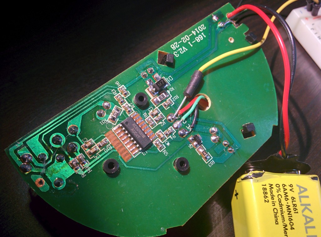
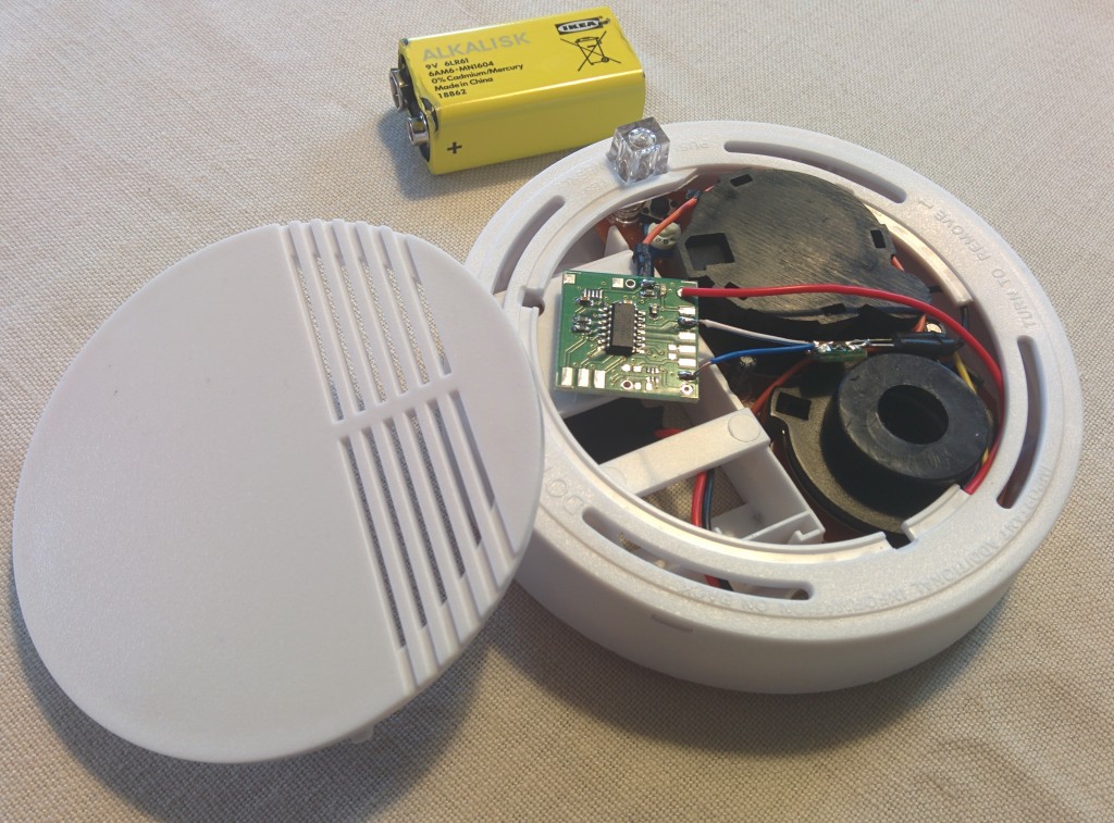
I purchased a battery operated smoke/fire alarm few days ago and it showed up today. It runs on 9V and will make a loud sound if smoke is detected. My intention was to hook it up with my home automation system so that I would receive alert if it would go off including SMS, pushbullet notification to my phone, email etc.
The Funky v1 is ideal for the purpose because it is really flat/tiny and would fit inside the alarm. It will tap into the piezo siren and sleep until the siren is activated. Upon activation, it will make a wireless transmission to my home automation system (Raspberry Pi running Node-Red) for further processing and alerting me on my phone.
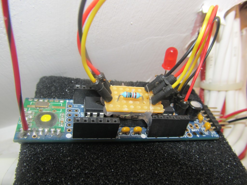
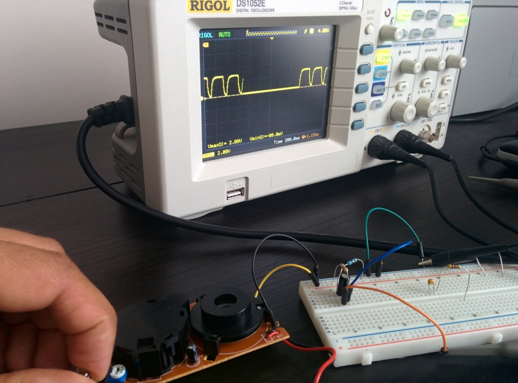
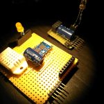
The piezo siren is activated with a 200ms series of 6.5Khz 50% PWM at 9V so I had to create a small voltage divider + a capacitor to smoothen the signal out and bring it to 3V so the Funky v1 can handle it. A 4.7K:10K + 1 uF ceramic capacitor works well:
![2014-07-19 16.10.18]()
![2014-07-19 16.11.12]()
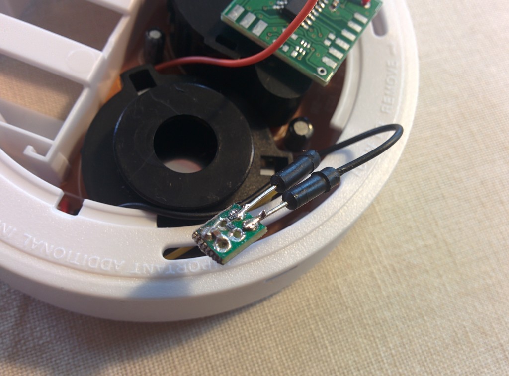
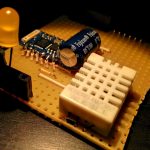
I then created a miniature PCB using 0603 sized SMD components for the voltage divider and low pass filter so that all can fit in the fire alarm sensor:
![2014-07-19 16.23.12]()
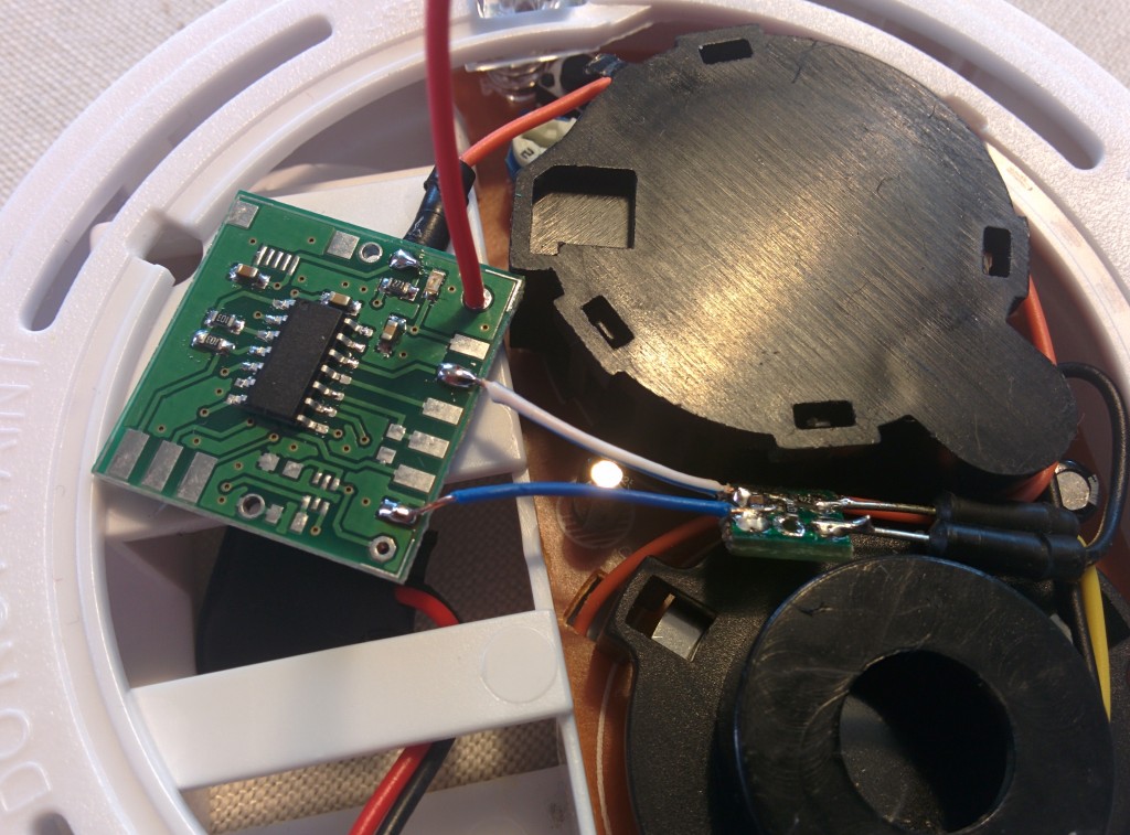
The Funky v1 is equipped with a MCP1703 LDO that will supply 3.3V from the available 9V.
![2014-07-19 16.33.53]()
![2014-07-19 16.35.06]()
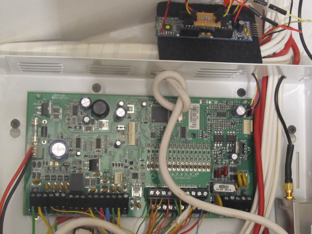
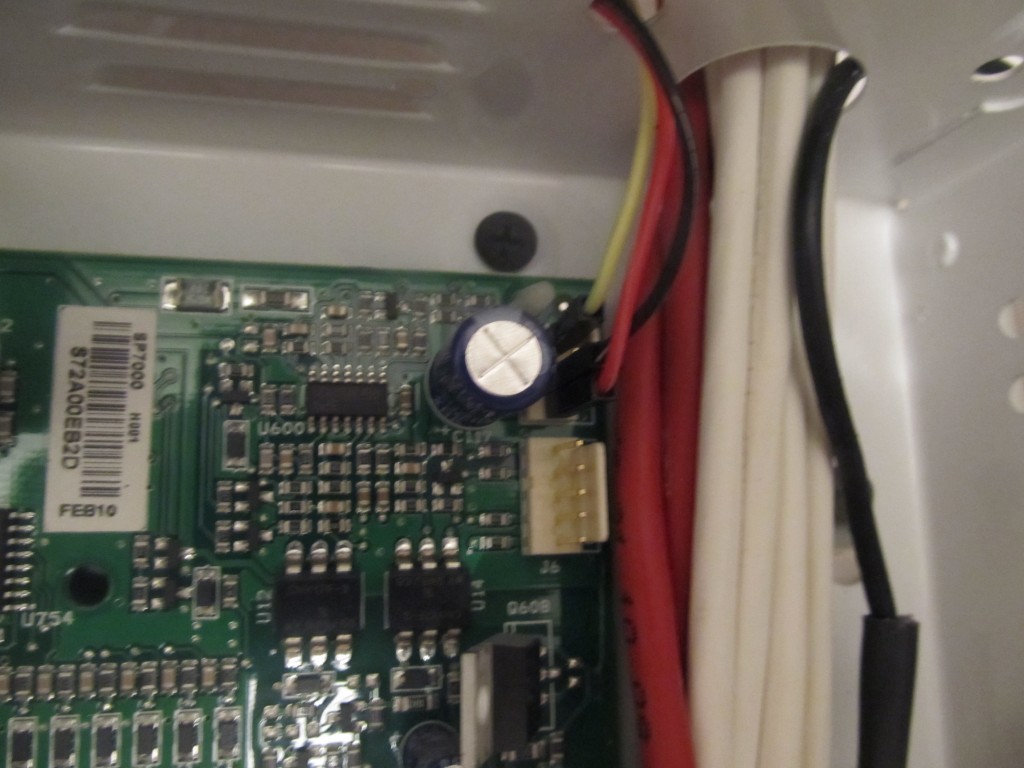
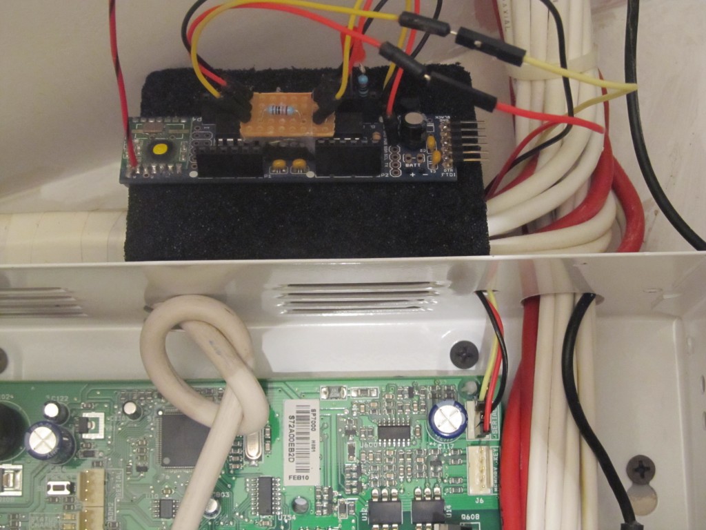
Everything is fit inside the original case.
The Funky is running the following code, basically it sleeps waiting for a pin-change interrupt from the piezo siren to kick in. It will wake every 30 min to provide heartbeat transmission and let the home automation system know it is alive and well.
//--------------------------------------------------------------------------------------
// harizanov.com
// GNU GPL V3
//--------------------------------------------------------------------------------------

#include <avr/sleep.h>

#ifndef cbi
#define cbi(sfr, bit) (_SFR_BYTE(sfr) &= ~_BV(bit))
#endif
#ifndef sbi
#define sbi(sfr, bit) (_SFR_BYTE(sfr) |= _BV(bit))
#endif

#include <JeeLib.h> // https://github.com/jcw/jeelib
#include "pins_arduino.h"

ISR(WDT_vect) { Sleepy::watchdogEvent(); } // interrupt handler for JeeLabs Sleepy power saving

#define myNodeID 13      // RF12 node ID in the range 1-30
#define network 210      // RF12 Network group
#define freq RF12_868MHZ // Frequency of RFM12B module

#define RETRY_PERIOD 5    // How soon to retry (in seconds) if ACK didn't come in
#define RETRY_LIMIT 5     // Maximum number of times to retry
#define ACK_TIME 10       // Number of milliseconds to wait for an ack


#define LEDpin 10


//########################################################################################################################
//Data Structure to be sent
//########################################################################################################################

 typedef struct {
  	  int state;	// State
 } Payload;

static Payload temptx;
static int gotPCI;

 ISR(PCINT0_vect) {
  temptx.state=bitRead(PINA,1);
  gotPCI=true;
 }

void setup() {

  pinMode(LEDpin,OUTPUT);
  digitalWrite(LEDpin,LOW);
  delay(1000);
  digitalWrite(LEDpin,HIGH);

  pinMode(9,INPUT);

  rf12_initialize(myNodeID,freq,network); // Initialize RFM12 with settings defined above
  // Adjust low battery voltage to 2.2V
  rf12_control(0xC040);
  rf12_sleep(0);                          // Put the RFM12 to sleep
//  Serial.begin(9600);
  PRR = bit(PRTIM1); // only keep timer 0 going
  gotPCI=false;
}

void loop() {

  pinMode(LEDpin,OUTPUT);

  digitalWrite(LEDpin,LOW);   // LED on
  Sleepy::loseSomeTime(100);
  digitalWrite(LEDpin,HIGH);  // LED off

  if(gotPCI) {  // How did we get here? Thru PinChangeInterrupt or wait expired?)
    temptx.state=1;
    rfwrite(); // Send data via RF
    Sleepy::loseSomeTime(65000); //JeeLabs power save function: enter low power mode for 60 seconds (valid range 16-65000 ms)
  }

  temptx.state=0;  // Set the doorbell status to off
  rfwrite(); // Send data via RF

  Sleepy::loseSomeTime(10000);  //sleep some more to debounce

  sbi(GIMSK,PCIE0); // Turn on Pin Change interrupt
  sbi(PCMSK0,PCINT1); // Which pins are affected by the interrupt

  gotPCI=false;
  for(int j = 1; ((j < 30) && (gotPCI==false)); j++) {    // Sleep for 30 minutes
    Sleepy::loseSomeTime(60000); //JeeLabs power save function: enter low power mode for 60 seconds (valid range 16-65000 ms)
  }

//  set_sleep_mode(SLEEP_MODE_PWR_DOWN); // Set sleep mode
//  sleep_mode(); // System sleeps here

  cbi(GIMSK,PCIE0); // Turn off Pin Change interrupt

}

//--------------------------------------------------------------------------------------------------
// Send payload data via RF
//--------------------------------------------------------------------------------------------------
static void rfwrite(){
   bitClear(PRR, PRUSI); // enable USI h/w
   for (byte i = 0; i <= RETRY_LIMIT; ++i) {  // tx and wait for ack up to RETRY_LIMIT times
     rf12_sleep(-1);              // Wake up RF module
      while (!rf12_canSend())
        rf12_recvDone();
      rf12_sendStart(RF12_HDR_ACK, &temptx, sizeof temptx);
      rf12_sendWait(2);           // Wait for RF to finish sending while in standby mode
      byte acked = waitForAck();
      rf12_sleep(0);              // Put RF module to sleep
      if (acked) { return; }

   Sleepy::loseSomeTime(RETRY_PERIOD * 1000);     // If no ack received wait and try again
   }
   bitSet(PRR, PRUSI); // disable USI h/w
}

// Wait a few milliseconds for proper ACK
 static byte waitForAck() {
   MilliTimer ackTimer;
   while (!ackTimer.poll(ACK_TIME)) {
     if (rf12_recvDone() && rf12_crc == 0 &&
        rf12_hdr == (RF12_HDR_DST | RF12_HDR_CTL | myNodeID))
        return 1;
     }
   return 0;
 }
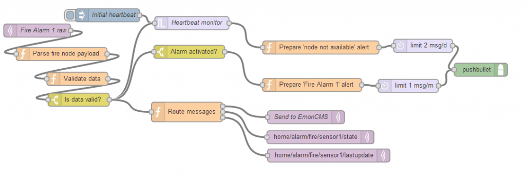
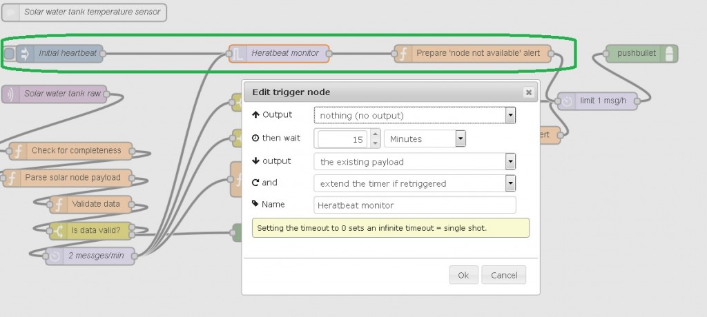
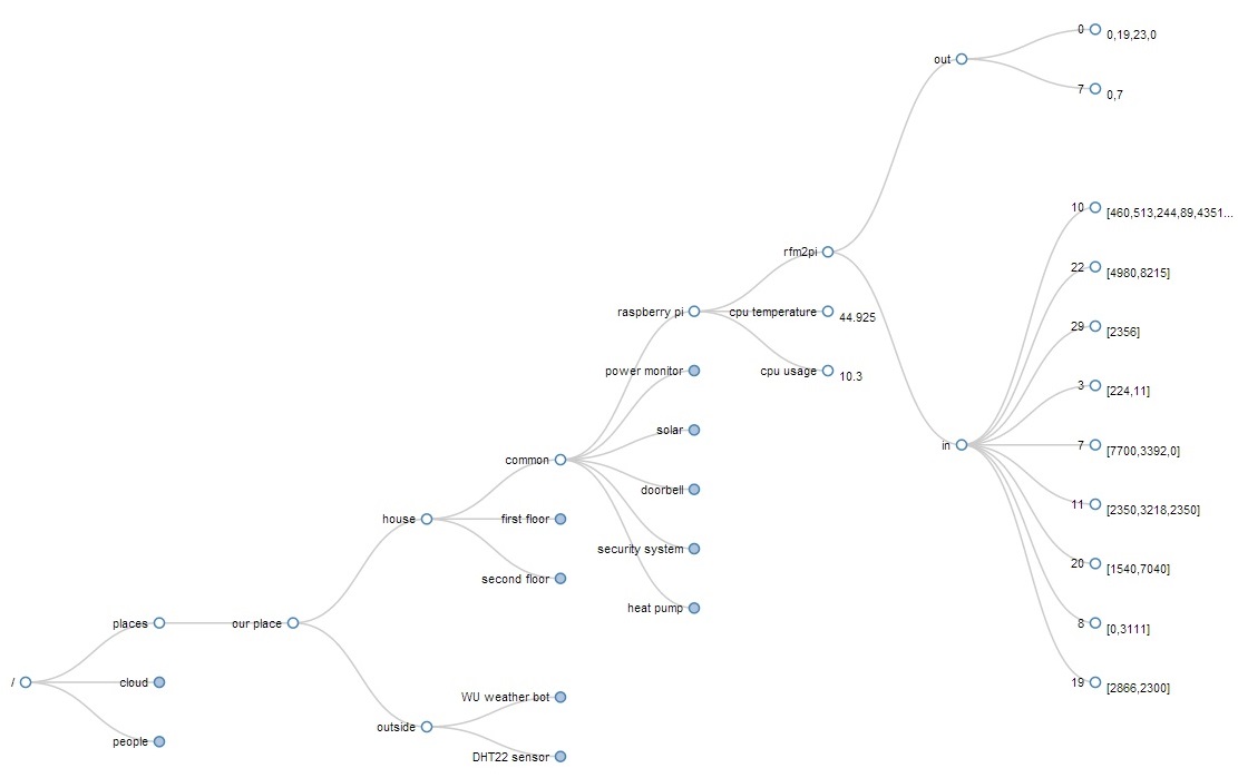
The receiving end is Raspberry Pi with RFM2Pi board running a read-only Raspbian. All the business logic is implemented using a Node-Red flow:
![Fire Alarm Flow]()
The flow consists of the following components
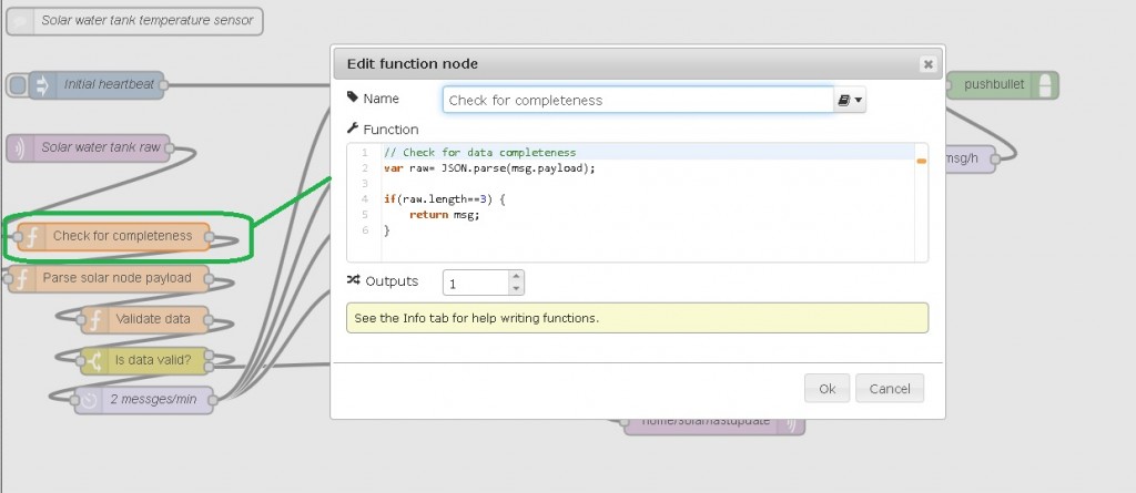
1) Parser that analyzes the raw payload
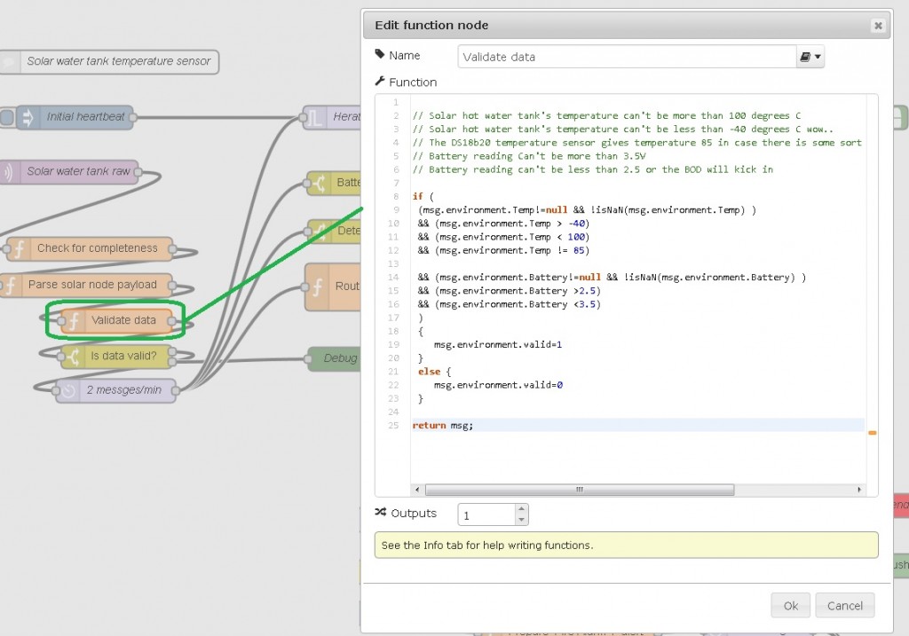
2) Data validator that makes sure the payload exists and contains the expected range of values
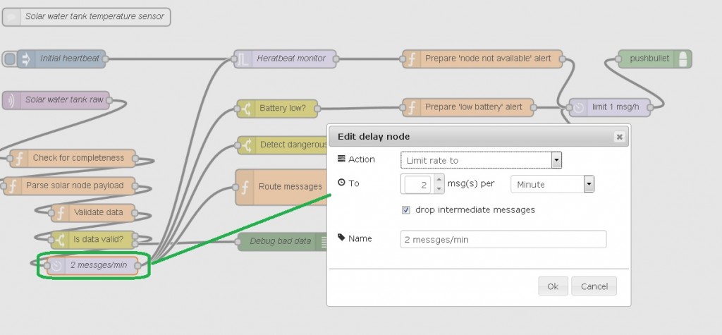
3) Heartbeat monitor to make sure we hear from the fire alarm often enough meaning it is up and running
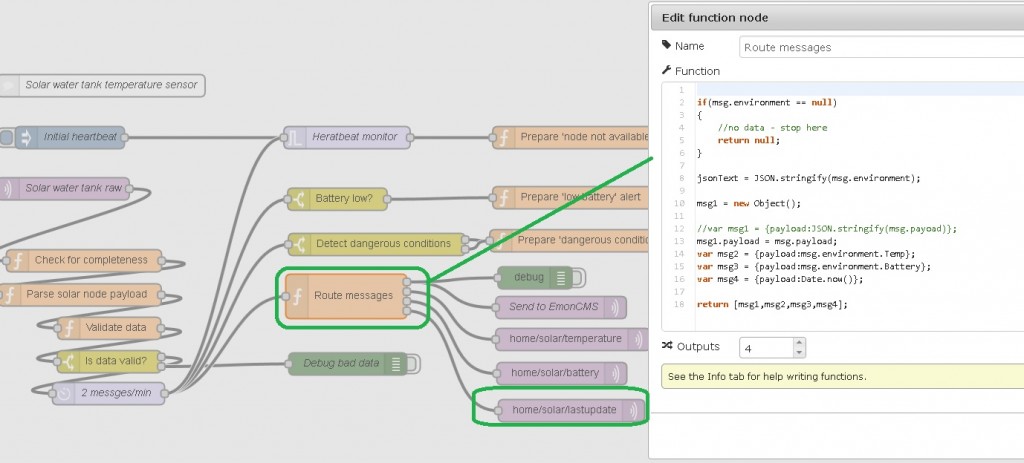
4) Alarm activated notification
5) logging to EmonCMS
Here is the code for the flow:
[{"id":"ba386057.845d3","type":"mqtt-broker","broker":"localhost","port":"1883"},{"id":"35befc4f.ca4104","type":"mqtt in","name":"Fire Alarm 1 raw","topic":"home/fire/alarm1","broker":"ba386057.845d3","x":97.22221374511719,"y":1891.222255706787,"z":"31c82d7c.ce37d2","wires":[["c0c8d3dc.3f373"]]},{"id":"214c6848.deb398","type":"pushbullet","title":"","name":"","x":1112.2222137451172,"y":1981.222255706787,"z":"31c82d7c.ce37d2","wires":[]},{"id":"c0c8d3dc.3f373","type":"function","name":"Parse fire node payload","func":"var raw= JSON.parse(msg.payload);\nmsg.environment = new Object();\n\nmsg.environment.AlarmState= (raw[0]); \n\nreturn msg;","outputs":1,"x":153.2222137451172,"y":1945.222255706787,"z":"31c82d7c.ce37d2","wires":[["18d0cda9.e72f32"]]},{"id":"8d10e00f.72ef2","type":"delay","name":"","pauseType":"rate","timeout":"5","timeoutUnits":"seconds","rate":"2","rateUnits":"day","randomFirst":"1","randomLast":"5","randomUnits":"seconds","drop":true,"x":980.2222137451172,"y":1926.222255706787,"z":"31c82d7c.ce37d2","wires":[["214c6848.deb398"]]},{"id":"18d0cda9.e72f32","type":"function","name":"Validate data","func":"\nif (\n (msg.environment.AlarmState!=null && !isNaN(msg.environment.AlarmState) )\n && (msg.environment.AlarmState >= 0) \n && (msg.environment.AlarmState < 2)\n ) \n {\n \tmsg.environment.valid=1\n }\n else {\n \tmsg.environment.valid=0\n }\n\nreturn msg;","outputs":1,"x":189.2222137451172,"y":2002.222255706787,"z":"31c82d7c.ce37d2","wires":[["3e25e8b5.c1da18"]]},{"id":"3e25e8b5.c1da18","type":"switch","name":"Is data valid?","property":"environment.valid","rules":[{"t":"eq","v":"1"}],"checkall":"true","outputs":1,"x":192.2222137451172,"y":2050.222255706787,"z":"31c82d7c.ce37d2","wires":[["d5f0b640.2a0f48","fb09e85c.04f618","2df65c73.d209a4"]]},{"id":"d5f0b640.2a0f48","type":"trigger","op1":"","op2":"1","op1type":"nul","op2type":"pay","duration":"45","extend":"true","units":"min","name":"Heartbeat monitor","x":451.2222137451172,"y":1874.222255706787,"z":"31c82d7c.ce37d2","wires":[["ced533d2.312ad"]]},{"id":"b1434385.4ebcc","type":"inject","name":"Initial heartbeat","topic":"","payload":"","payloadType":"date","repeat":"","crontab":"","once":true,"x":258.2222137451172,"y":1856.222255706787,"z":"31c82d7c.ce37d2","wires":[["d5f0b640.2a0f48"]]},{"id":"fb09e85c.04f618","type":"switch","name":"Alarm activated?","property":"environment.AlarmState","rules":[{"t":"eq","v":"1"}],"checkall":"true","outputs":1,"x":445.2222137451172,"y":1940.222255706787,"z":"31c82d7c.ce37d2","wires":[["b7b3e435.484c18"]]},{"id":"ced533d2.312ad","type":"function","name":"Prepare 'node not available' alert","func":"msg.payload= \"Haven't heard from Alarm1 sensor node for a while..\";\nmsg.topic=\"Fire alarm 1 not available!\";\nreturn msg;\n","outputs":1,"x":746.2222137451172,"y":1930.222255706787,"z":"31c82d7c.ce37d2","wires":[["8d10e00f.72ef2"]]},{"id":"b7b3e435.484c18","type":"function","name":"Prepare 'Fire Alarm 1' alert","func":"msg.payload= \"Fire Alarm 1 sensor activated !!!\";\nmsg.topic=\"Fire Alarm 1!!!\";\nreturn msg;","outputs":1,"x":726.2222137451172,"y":2016.222255706787,"z":"31c82d7c.ce37d2","wires":[["6351719c.9cae9"]]},{"id":"2df65c73.d209a4","type":"function","name":"Route messages","func":"// The received message is stored in 'msg'\n// It will have at least a 'payload' property:\n// console.log(msg.payload);\n// The 'context' object is available to store state\n// between invocations of the function\n// context = {};\n//create json text\n\nif(msg.environment == null)\n{\n\t//no data - stop here\n\treturn null;\n}\n\njsonText = JSON.stringify(msg.environment);\n \n//var msg1 = {payload:JSON.stringify(msg.environment)};\nvar msg1 = msg.payload;\nvar msg2 = {payload:msg.environment.AlarmState};\nvar msg3 = {payload:Date.now()};\n\nreturn [msg1,msg2,msg3];","outputs":"3","x":440.2222137451172,"y":2078.222255706787,"z":"31c82d7c.ce37d2","wires":[["c616e74e.39e918"],["3526f324.cad90c"],["e4a17c3e.1b5e8"]]},{"id":"c616e74e.39e918","type":"mqtt out","name":"Send to EmonCMS","topic":"/home/emoncms/out/13","broker":"ba386057.845d3","x":712.2222137451172,"y":2090.222255706787,"z":"31c82d7c.ce37d2","wires":[]},{"id":"3526f324.cad90c","type":"mqtt out","name":"","topic":"home/alarm/fire/sensor1/state","broker":"ba386057.845d3","x":745.2222137451172,"y":2136.222255706787,"z":"31c82d7c.ce37d2","wires":[]},{"id":"e4a17c3e.1b5e8","type":"mqtt out","name":"","topic":"home/alarm/fire/sensor1/lastupdate","broker":"ba386057.845d3","x":764.2222137451172,"y":2178.222255706787,"z":"31c82d7c.ce37d2","wires":[]},{"id":"6351719c.9cae9","type":"delay","name":"","pauseType":"rate","timeout":"5","timeoutUnits":"seconds","rate":"1","rateUnits":"minute","randomFirst":"1","randomLast":"5","randomUnits":"seconds","drop":true,"x":946.2222137451172,"y":2018.222255706787,"z":"31c82d7c.ce37d2","wires":[["214c6848.deb398"]]}]
I then closed up everything, added a ‘hacked’ sticker and tested it above a burning piece of paper. My phone was alerting me a second later.. neat.
![Fire Alarm IoT]()
And a video of it in action:
As a conclusion this DIY solution costs fraction of the price of similar commercial products (like the Nest Protect for example) and is way more flexible as well.
(1839)
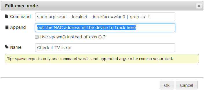
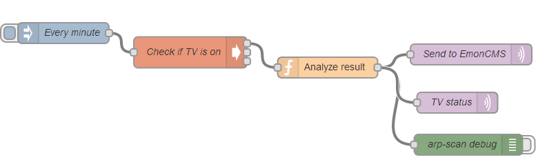 The TV check function is an exec node-red module that runs the arp-scan command: