As you may have noticed, the publication date of these posts has been shifting a bit. Well, no longer: from now on, all posts will be scheduled to go out on … Weekly Wednesday!
As before, each post will mention one or more new articles, released on successive days.
This “Getting Started” series has been about exploring ARM µC’s, in particular the 8-pin LPC810 shown above, and there’s one important topic left to cover so you can compile your own code and explore what’s possible in this virtually infinite playground.
Here goes, the concluding articles of the Getting Started series:
If you’re eager to start tinkering with the LPC810 chip: have a look at the JeeLabs shop, where Martyn Judd & Co from Digital Smarties have created two very practical packages to get you started: the Bare ARM Blinker kit which has everything needed to replicate and extend the recent explorations on this weblog, and the ARM duo- and 6-pack, i.e. a supply of bare LPC810 chips to experiment with. Note that there’s no soldering involved.
Be warned, though: it’s pretty addictive stuff!– and we’re only just getting started…
Une interface sans contact pour téléphone portable
Le thérémine est un instrument de musique, inventé en URSS, par Lev Termen, en 1919. Il se joue sans contact.
Le principe est simple. Un son de base est produit par un dispositif électronique. Le joueur de Thérémine module ce son en hauteur et en volume en variant la distance de ses mains vis a vis de deux antennes. Le phénomène de “capacitance” permettant ces variations est connu de toutes personnes se déplaçant à proximité d’une radio FM en faisant des “interférences”
Sur ce principe de capacitance, nous pourrions imaginer un dispositif simple, robuste et original permettant d’interagir avec nos téléphones, tablettes, ordinateurs? Qu’ils soient apaisés ou de dernière génération.
Objetcifs :
Proposer une interface alternative au tactile pour interagir avec nos machines.
Imaginer des applications ne nécessitant pas l’usage de l’écran
Proposer une nouvelle interface, c’est proposer au créateur d’application de nouveaux scénario d’usages pour nos équipements et ouvrir une voie pour de nouveaux projets.
Si un ensemble de 2 antennes peut convertir n’importe quel smartphone/tablette en thérémine, il est évident que l’interaction sans contact devrait permettre d’imaginer des usages totalement en rupture avec ce qui est proposé actuellement pour l’ensemble de nos équipement.
Avantages
Redonner une place aux corps et aux mouvements amples dans la manipulation d’applications sur téléphone
Permettre des applications ne faisant pas appel au tactile et à l’écran.
Sortir de la standardisation des usages de l’électronique grand public, (ici du tout tactil sur écran minuscule) pour repenser les usages, les besoins, c’est ouvrir une porte à la réflexion sur ces objets monolithiques omniprésents que sont nos smartphones.
This next article series is about setting up a practical project for use around the house. It’s small enough to be covered in a few articles, and simple enough to be constructed entirely on a breadboard with no soldering involved. It’s time to start making things!
I’ll take you through the problem definition, the way to pick a solution, and the many trade-offs involved in getting everything working as intended. As you will see, getting this thing to run off batteries poses some challenges, but is nevertheless feasible.
Here are this week’s articles, as planned for the coming days at 0:00 CET:
The GPA has all the properties you’d expect in a physical computing project: a sensor, a readout, a microcontroller, and a power source. You may not have a garage (or a car), or you may have a car with this functionality built-in, but there’s probably something to glean from this design process for your own use – and maybe some parts will be useful in other ways. It’s all “loosely coupled” after all, with a breadboard to build any variations you like:
Speaking of parts – Martyn & Co have produced a kit for the JeeLabs shop if you’d like to get going fast, with everything needed to create this little parking aid gimmick.
Getting to know the ARM architecture and the LPC810 is a wonderful adventure. It’s also almost impossible to figure out where to start. So let’s just dip our toes in the water, eh?
This week’s articles all highlight a different aspect of the LPC810 (of the entire LPC8xx series, in fact), by exploring a variety of uses and figuring out how to implement them.
Each of the following examples includes a minimal circuit to demonstrate their use:
All of them can also be built on a breadboard, but soldering up a little circuit with an 8-DIP chip (or socket) in them is a lot more fun. It really shows the versatility of such little µC’s:
Who knows, you might even have an immediate use for some of these examples. With a bit of extra work, any of them could be turned into a self-contained I2C slave to add to your own project. Instead of complicating your own project code with the hard timing requirements of pulsed LEDs or servos, why not simply “off-load” to a dedicated LPC810?
The sky is the limit. Eh, wait, strike that, it isn’t anymore…
The past several weeks were about hacking stuff together: electrically connecting chips and some other components together, and making the resulting circuit + software do fun stuff.
This week is about turning an experiment into a more formal design.
In some cases, such as the mains distribution panel at JeeLabs, clear wiring is not a luxury:
Those colour codes are not for making a pretty picture – the are required by law. And even though most mains distribution panels end up being unique one-offs, the formal “notation” is essential to make each design well-documented and understandable for decades to come.
With low-power experiments, we have a lot more freedom to just hack around, fortunately!
But although breadboards are great for trying out ideas by letting you “edit” the electronic circuit, at some point you will probably want to make it more permanent, or smaller, or more robust – or even all those at once. Or perhaps you simply want to make it repeatable, so more “instances” of your experiment can be produced – whether for fun or for profit, and perhaps even not for yourself but for others to replicate with minimal effort.
Tinkering is fun. Repeatedly solving the same puzzle or falling into the same trap is not.
Here are this week’s articles, as planned for the coming days at 0:00 CET:
Please note that these articles are not a how-to guide for the entire process, just a first introduction to all the steps involved in going from an idea to a reproducible design.
Physical computing is about hooking things up. Sure, there’s also low-power and wireless in the mix, but in the end you need to tie into the real world, and that means connecting sensors, indicators, actuators, and what-have-you-not. It’s a big varied world out there!
The computing side is all about information. From a µC’s perspective, we need to direct information from sensors to us, and from us back out to indicators and actuators.
The more data you need to shuttle across (or the more frequently), the harder it becomes in terms of engineering. But sometimes all you need is to send or receive a few bytes of data, perhaps just a few times per second. That’s where I2C comes in, created over 30 years ago.
Or, more accurately: the I²C bus, which stands for the “Inter-Integrated Circuit” bus.
So the upcoming article series is about this wickedly clever “eye squared see” invention:
As before, one article per day. And while we’re at it, I’ll also use the Raspberry Pi single-board computer as an example of how to use I2C under Linux. As you’ll see, it’s really easy!
Dynamic DNS support so that the module’s IP is always known
I2C status display support
Custom made plastic box/cover
Scheduling functionality
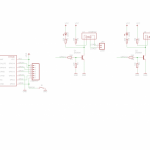
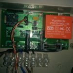
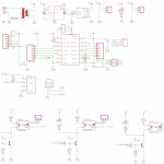
I’ve created a prototype PCB to test the concept, used a quick turnaround PCB service that was neither quick nor of good quality. The initial idea was something like this:
The v1 board had some design flaws, but overall works well. Here is a video, the software was at early stage then:
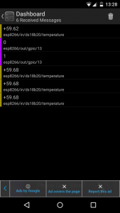
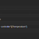
I’ve since then added native MQTT support based on Martin Hubáček’s mbed MQTT for LwIP. That implementation is quite basic and lacks some features so I plan to replace it with Tuan PM’s fresh MQTT for ESP8266 code in the future. The board currently publishes the readings of the DS18B20 temperature sensor to “ESP8266/in/ds18b20/temperature” topic and subscribes itself to “ESP8266/out/gpio/#” to watch for on and off commands for the three SSRs on GPIOs 12-14. The publish and subscribe topics are hardcoded now, but I am working on a configuration web interface where all these settings would be exposed.
MQTT makes it quite easy to implement external business logic, I use Node-Red for the purpose and have implemented complex rules that trigger my boiler heater element and a heat exchanger contour TRV.
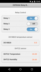
I also added a jQuery powered control UI with background refresh using the board’s HTTP/JSON API; it updates automatically if the state changes from another session or MQTT control packet.
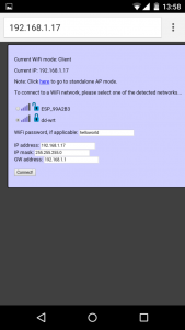
The configuration UI is intentionally in the old-style plain HTML so that it can be rendered even when the board is in AP configuration mode and the connected device can’t pull the jQuery libraries online.
NTP support is also there and I plan to use that for some basic scheduling functionality; Given the HTTP API and MQTT support, that seems less and less practical, but I still do plan to add it at some point in time.
Alternatively, one could use the nodeMCU ESP8266 Lua firmware instead and make all sorts of fancy use of the relay board with custom scripting some thermostat functions for example.
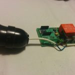
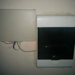
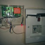
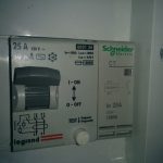
I’ve used the v1 board to control a contactor that switches on and off the heater element in my boiler and controls a Non-Mechanical Thermo Electric Actuator that opens heat exchanger contour in case my fireplace with water jacket produces hot water that exceeds the boiler’s current temperature and thus aids or completely replaces the electric heater element:
The HTTP API exposes the status of the relays and sensors as JSON string
http://IP/gpio.cgi returns the state of the relays { “gpio12″: “0”,”gpio13″: “0”,”gpio14″: “0”}
Relays are switched on/off using a query string: http://IP/gpio.cgi?gpio12=1&gpio13=0&gpio14=0
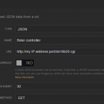
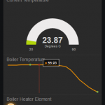
Since the module can provide JSON status string, we can use freeboard.io to query and visualise the data directly with no proxying, I have only set a router rule to port forward the http traffic of an externally visible port to port 80 of the Relay board:
So the relay now talks to freeboard.io, a 3 minute effort to illustrate the power of the Internet of Things.
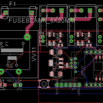
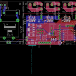
I’ve decided to swap the 2A relays I used in v1 of the board with 8A ones and also made some fixes to the board design, here are the plans for v2:
I will be ordering few test boards of the v2 and blogging my progress once they are with me.
Switching larger loads is quite easy by adding a AC-AC SSR on top, I suggest Fotek’s line like this one. Connecting SSRs in parallel to increase the load current is *NOT* an option, just a note to those curious to try (myself included).
Once I get all this working as I imagine it, I will make the board design files and source code available on Github, and will offer a limited number of pre-built boards in my shop. You want one, trust me.. Follow me on Twitter to get the news first when these are available. Follow @mharizanov (478)
This week, as we jump from 2014 into 2015, I’d like to start on an exploration which is dear and near to me: ultra low-power wireless sensor nodes for use in and around the house.
The LPC810 µC has 4 free I/O pins, when connected via a serial port or I2C. And as it so happens, it’s also quite feasible to drive an RFM69 wireless module with just 4 pins, i.e. using just an SPI bus connection, without any interrupt pins hooked up.
So why not try to combine the two, eh?
The following articles introduce a brand new “RF69″ driver, using native packet mode:
This concludes this year’s refreshed weblog series, but I’m really looking forward to the year ahead. The new weekly format is working out nicely for me – I hope you also like it.
To close off the year and fulfil another goal I had set for myself, the recent material on this weblog has now been added to the The Jee Book. It’s just a start to let you download the entire set of articles published so far – in a range of e-book formats, including PDF.
I hope you had a great 2014 and wish you a very Guten Rutsch into 2015. May it bring you and yours much happiness, creativity, and inspiration – with respect and tolerance for all.
The code presented last week – or should I say last year?– was unfinished. In fact, it wasn’t even tested, just designed and written in a way which “should” work, eventually…
The thing with communication is that you’ve got two pieces which need to work together, but they are running on different bits of hardware, which makes it harder to see the big picture and reason about what’s going on. Getting to that first data exchange can be tricky.
In this case, we’ve also got an I2C link in there, so there are in fact three systems involved, and in addition, we’re going to need a way to re-program those two LPC810 µC’s:
Let’s get on with it and figure out how to make this stuff work:
En 2017, selon un rapport de l’ONU, 65 millions de tonnes de déchets électroniques (ordinateurs, téléphones…) seront produits chaque année.
A l’échelle mondiale, moins de 20% des déchets sont recyclés.
Concept
Organiser un concert dans une des grandes décharges d’électronique avec des instruments fabriqués à partir des déchets collectés sur place.
En Afrique ou en Asie : Ghana, Mali, Pakistan, Chine…
Des musiciens joueront avec des instruments électroniques fabriqués à partir de déchets collectés sur place.
Les instruments seront développés en collaboration avec des Makers spécialistes de l’électronique pendant un atelier d’une semaine.
Le concert sera organisé en collaboration avec des partenaires locaux, institutionnels et ONG.
Le concert et sa préparation seront filmés afin de réaliser un film documentaire, trace de l’expérience.
Objectifs
Parler des déchets électroniques via un dispositif à contre pied des documentaires alarmistes.
Favoriser l’émergence d’objets électroniques recyclés, témoins manifestes du rythme effréné de notre consommation.
Des instruments de type “Toys made in décharge” ou “théremine on the go” (projets présentés ici même) pourraient être des bonnes pistes d’instruments à développer et produire pour le concert.
The “LPC810 meets RFM69″ series, is being postponed a bit longer than anticipated, the relevant pieces are simply not ready and stable enough yet to present as working code. With my apologies for this change of plans. I’ll definitely get back to this – count on it!
For now, let’s start exploring another piece of the puzzle, when it comes to setting up a wireless network, and in particular a wireless sensor network (WSN).
As usual, each of the above articles will be ready on subsequent days.
If you’ve always wanted to try out Linux without messing with your computer – here’s a gentle introduction to the world of physical computing, from a Linux board’s perspective!
There is a lot more to go into w.r.t. the LPC810 µC and the RasPi/Odroid Linux boards, but since surprisingly many design decisions are related to that main driving force of electricity called “voltage”, this is a good opportunity to first cover those basics in a bit more detail.
Here is the list of upcoming articles, one per day:
Here’s a nice diagram from Wikipedia with all the rechargeable battery technologies:
Quite a variety, and all of them with different trade-offs. Read the articles to find out why it matters, when to stack ‘em up, how to avoid problems, and what buck & boost is about.
Like many people I have been playing with the Espressif ESP8266 WiFi modules over the last few months. I’ve had a couple of modules running for a while now, one connected to an Arduino pro mini clone with a 2×16 OLED display and one running directly on the ESP8266 using the NodeMcu Lua interpreter controlling a relay over an HTTP REST-like API.
One thing I was really hoping for was a native MQTT implementation as it is the protocol I use for my home automation and sensor network. Luckily tuanpm on the esp8266.com forums gave us a boxing day present in the form of a native MQTT client. MQTT on the ESP8266 means it will be easy to integrate input and output nodes in to my existing home automation and sensor network.
For a first test I just changed the MQTT and WiFi settings in user_config.h, tweaked the Makefile for my environment and compiled with the esp-open-sdk toolchain (currently with the 0.9.3 Espressif SDK, I need to update) and it compiled fine, I flashed it to the ESP8266 and gave it a test run on a busy MQTT topic (all my environmental sensors) for a day or so and it handled it without a problem.
The following day I hooked up a spare 0.96″ I2C OLED display and soon had it showing data from my sensors.
This demo is using the common ESP-01 variant of the ESP8266 board, available on eBay from Chinese sellers for around £2 each or a bit over double that from UK sellers. The downside of this module is that it only has two GPIO pins and we need both of those for the I2C and GPIO0 also to be grounded when we want to get into programming mode, a minor inconvenience but I also have some ESP-03 boards that I am working on a PCB for, as well as an ESP-12 and some ESP-WROOM modules that I got as a freebie from Espressif, all these have a lot more available GPIO pins.
The demo C code is available here, it’s hardcoded to my setup but it should get you going if you want to give it a try.
It subscribes to three MQTT topics and displays them on the OLED (two temperature feeds and an info message on the bottom of the screen), the display I am using is this 0.96″ 128×64 White OLED but similar displays are widely available (plenty on eBay).
Configuration
I2C address for the OLED is in include/driver/i2c_oled.h
MQTT broker and WiFi settings are in include/user_config.h
GPIO pins to use for I2C are in driver/i2c.h
MQTT topics to subscribe to are in the MQTT_Start() function in user/mqtt.c
What to do with the incoming messages is defined in deliver_publish() in user/mqtt.c
If you want to add more than 3 topics you will need to change MQTT_SUB_TOPIC_NUM in user_config.h and the mqtt_topic variable declaration near the top of mqtt.c
I use Linux so I haven’t tested the Windows Makefile, it is as it comes with the MQTT demo but should work provided the SDK & tool paths are correct for your build environment.
Hardware wise it is just 3v3 to VCC and CH_PD on the ESP8266 and VCC on the OLED, ground on both and SDA on the OLED to GPIO2 and SCK to GPIO0.
This is just a quick demo for now but I’ve got a few ideas where it could be useful, I might do a custom PCB using the ESP-03 plus a regulator and maybe a DS18B20 sensor and a button or two.
Update 31/12/14: I was asked to add some more info on how to get this onto the ESP8266 for someone new to it so here is the complete process from installing the toolchain/SDK through to compiling and flashing to the ESP8266. I’ve done this from memory but I don’t think I’ve missed anything.
Make sure you have all the prerequisites installed, on Ubuntu 14.04 this can be done with:
sudo apt-get install make unrar autoconf automake libtool gcc g++ gperf flex bison texinfo gawk ncurses-dev libexpat-dev python sed
Grab the esp-open-sdk from the Github, either with git:
This will download all the necessary toolchain and SDK files and compile them.
Install the other esptool– There are two different tools called esptool and with the current Makefile you need both. esptool.py is a python tool that is used to flash the .bin files to the ESP8266 and is installed with the esp-open-sdk process above.
With the current Makefile you will also need the binary esptool from here, this one creates the firmware .bin files (esptool.py can create .bin files too, it just needs some changes to the Makefile).
Now back in the esp_mqtt_oled directory find the following lines in the Makefile to make sure they point to the location of the files you just installed:
Also make sure the ESPPORT is pointing to the location of your serial adapter, eg:
ESPPORT ?= /dev/ttyUSB2
Connect the ESP8266 to your 3.3v serial adapter, RX on the ESP8266 to TXD of the adapter and TX to RXD
You need 3.3v to the VCC and CH_PD pins on the ESP8266 and ground to GND.
you also need to connect GPIO0 to GND during power on to get it into programming mode.
You will probably find that your serial adapter cannot supply enough power for the ESP8266, in that case you will need to power it from an external 3.3v source, disconnect the 3.3v from the serial adapter but make sure the ground from the power source and the serial adapter are both connected.
Now from esp_mqtt_oled directory do:
make
This will compile and build the firmware, you should get no errors but the Warning messages are normal (actually just info). You should now have a firmware directory with two files: 0x00000.bin 0x40000.bin
Then to flash these firmware files to the ESP8266 do:
make flash
Now disconnect GPIO from ground and back to SCL on the OLED and restart the ESP8266 (power off/on). Hopefully you should see some startup messages on the OLED now: “ESP8266 MQTT OLED” then “WiFi connected” then “MQTT connected” and finally data from the MQTT topics you defined in mqtt.c should start to appear.
You can also do “make test” to connect to the serial output with screen or use another serial app at 115200 baud, eg. minicom with “minicom -b 115200 -D /dev/ttyUSB2”
If you want to change anything and reflash it is just a case of doing:
make clean make make flash
Hopefully that will save anyone new to this some time.
I’ve been meaning to hold a video Google hangout session on IoT topics for some time now, how about giving it a try?
I imagine it as informal 1 hr tech-talk with the following structure
35 min presentation of a certain topic by a community presenter
15 min comments, Q/A on the presented topic
10 min general chat and planning for next session
Picking convenient for everyone time/date may be tricky, myself being located at GMT+2 time zone. I am thinking that Monday evenings 9 PM my local time (GMT+2) may be a good candidate, so lets schedule the first hangout date for Monday, Feb 9th 2015 7 PM GMT. Use the meeting planner tool to check the local time for your location, mine is Sofia, Bulgaria.
Google video hangouts support only 10 participants at a time, so only that many can be allowed. I’ll see what are the options to record these sessions so folks can see what was discussed afterwards. I’ll pick 10 random and notify them by email that they are selected to participate by Feb 4th EOD.
The first session’s presenter will be yours truly and I plan to talk about my home automation system architecture.
I’ve set up a sign-up form for those interested: (54)
Let’s revisit the LPC810 and the RFM69. Things are starting to come together at last.
I’ll pick up where I left off three weeks ago, making two LPC810’s talk to each other via RFM69’s and then picking up the results on a Raspberry Pi over I2C. Hang in there!
Several people have mentioned these topics to me recently, as being something they’d like to know more about. All of it is available from various textbooks of course, but it’s often buried deeply in more elaborate chapters. It seems like a good idea to single these out, especially if you’re quite fluent in programming a higher-level language other than C/C++.
Interestingly, all these topics turn out to be related in some way to memory maps, such as this somewhat arbitrary example from Wikipedia:
Low level programming is all about wrestling with such details, very “close to the silicon”.
The other topics which tend to trip people up coming from JavaScript, Python, PHP, Java, etc. are about how bits, bytes, and words can be manipulated, how to deal with memory areas for arrays and buffers, how types work in C/C++, and how a CPU copes with urgency:
This week is about uploading firware over a serial communication link, and interacting with the uploaded firmware.
First a quick recap on how it all works, then a little diagnostic tool, and then a little utility with some new powers. Your Odroids and Raspberries will never be the same again!
The article schedule for the coming days is as follows:
It’s time to tackle a fairly ambitious challenge: let’s try to make an LPC810 run off “harvested” energy and use it to periodically send out a wireless packet.
This week will be a short intro into the matter, with more to follow later:
To lift the veil a bit, here’s the energy I’m going to try to harvest:
This is the voltage from a Current Transformer (CT), when unloaded. Such a CT needs to be “clamped” around one of the wires in an AC mains cable, and will then generate a voltage which is proportional to the amount of current flowing in that wire.
So far, there’s an idea, a circuit to collect energy, and sample code to make an LPC810 come alive every so often, briefly. It’s time to tie things together and see what happens!
As usual, one article per day in this week’s episode:
As you will see in Saturday’s article, this first MPS design is indeed able to power an LPC810 µC after some modifications, and keep it alive “under certain conditions”.
But there’s a very nasty skeleton in the closet – stay tuned!